Hybrid permanent magnet rotor assembly and corresponding motor

A permanent magnet, rare earth permanent magnet technology, applied in the direction of magnetic circuit rotating parts, magnetic circuit shape/style/structure, etc., can solve the problems of low motor magnetic flux, power drop, low surface magnetic flux density, etc., and prolong the service life , The effect of reducing material cost and reducing manufacturing cost

Active Publication Date: 2014-02-12
EMERSON CLIMATE TECH (SUZHOU) CO LTD
View PDF7 Cites 8 Cited by
  • Summary
  • Abstract
  • Description
  • Claims
  • Application Information

AI Technical Summary

Problems solved by technology

However, since the magnetic force lines forming a closed loop of the permanent magnets need to pass through the stacked rare earth permanent magnets 19 and the ferrite permanent magnets 20 simultaneously, the surface magnetic flux density of the stacked permanent magnets becomes lower , which results in a lower flux to the motor, which reduces its power

Method used


Image

  • Hybrid permanent magnet rotor assembly and corresponding motor
  • Hybrid permanent magnet rotor assembly and corresponding motor
  • Hybrid permanent magnet rotor assembly and corresponding motor

Examples


Embodiment Construction

[0019] The following description of preferred embodiments is exemplary only and in no way restricts the invention and its application or usage.

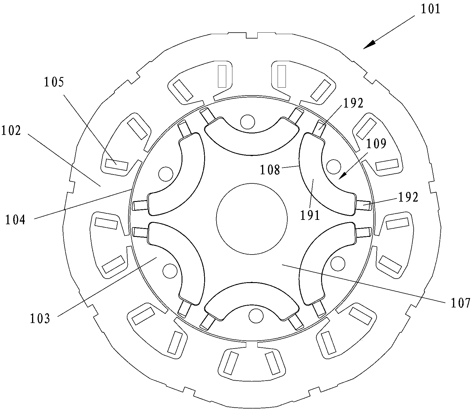
[0020] With reference to the accompanying drawings, figure 2 An interior hybrid permanent magnet motor 101 according to a preferred embodiment of the present invention is shown. The interior hybrid permanent magnet electric machine 101 includes a stator assembly 102 and a rotor assembly 103 within a cavity of the stator assembly 102 . According to known techniques for constructing rotating electrical machines, by using the rotor shaft, rotor bearings and end shields ( figure 1 not shown in ) to position the rotor assembly 103 within the lumen of the stator assembly 102 . The stator assembly 102 defines a plurality of stator teeth 104 extending in a radial direction thereof toward the interior cavity of the stator assembly 102, at figure 1 In the illustrated embodiment, there are 9 stator teeth 104, of course, the number of stator...


PUM


Abstract

The utility model relates to a hybrid permanent magnet rotor assembly, comprising a rotor core, a plurality of magnet containing grooves disposed in the rotor core, and a plurality of groups of hybrid permanent magnets disposed in the magnet containing grooves, wherein each group in the plurality of groups of hybrid permanent magnets comprises ferrite permanent magnets disposed on central positions of the magnet containing grooves and rare earth permanent magnets disposed on two side ends of the magnet containing grooves. The hybrid permanent magnet rotor assembly can effectively overcome a problem that a permanent magnet motor rotor in the prior art is easy to demagnetize, and through using the ferrite permanent magnets as a main part of the motor rotor permanent magnet, material cost of the motor rotor is greatly reduced. The utility model also relates to a motor using the hybrid permanent magnet rotor assembly.

Description

technical field [0001] The invention relates to a motor rotor assembly, especially a motor rotor assembly with hybrid permanent magnets, and also relates to a motor using the rotor assembly. Background technique [0002] In the prior art, interior permanent magnet motors are widely used due to their high efficiency. Ferrite permanent magnets or rare earth permanent magnets are generally used in permanent magnet motors. However, since the magnetic flux density of ferrite permanent magnets is low, which is generally half or less of that of rare earth permanent magnets, it is usually used in low-power motors. Although rare-earth permanent magnets have high magnetic energy density and can be used in high-power motors, the cost of motors using magnets made of them is greatly increased due to the lack of rare-earth element resources and high prices, which limits the Wide adoption of rare earth permanent magnet motors. Therefore, due to lack of resources and cost considerations,...

Claims


Application Information

Patent Timeline
Patent Type & Authority Applications(China)
IPC IPC(8): H02K1/27
Inventor 曹平山李欣李鑫
Owner EMERSON CLIMATE TECH (SUZHOU) CO LTD
Why Eureka
Try Eureka