Air floatation rotor heat dissipation structure and motor

A technology of heat dissipation structure and rotor, applied in the direction of magnetic circuit shape/style/structure, mechanical equipment, electric components, etc., can solve the problems of increasing the volume and cost of the motor cooling system

Active Publication Date: 2021-04-09
GREE ELECTRIC APPLIANCES INC OF ZHUHAI
View PDF9 Cites 0 Cited by
  • Summary
  • Abstract
  • Description
  • Claims
  • Application Information

AI Technical Summary

Problems solved by technology

However, this rotor cooling structure requires an external air source, and the motor needs to be equipped with an air pump, which greatly increases the volume and cost of the motor cooling system.

Method used


Image

  • Air floatation rotor heat dissipation structure and motor
  • Air floatation rotor heat dissipation structure and motor
  • Air floatation rotor heat dissipation structure and motor

Examples


Embodiment 1

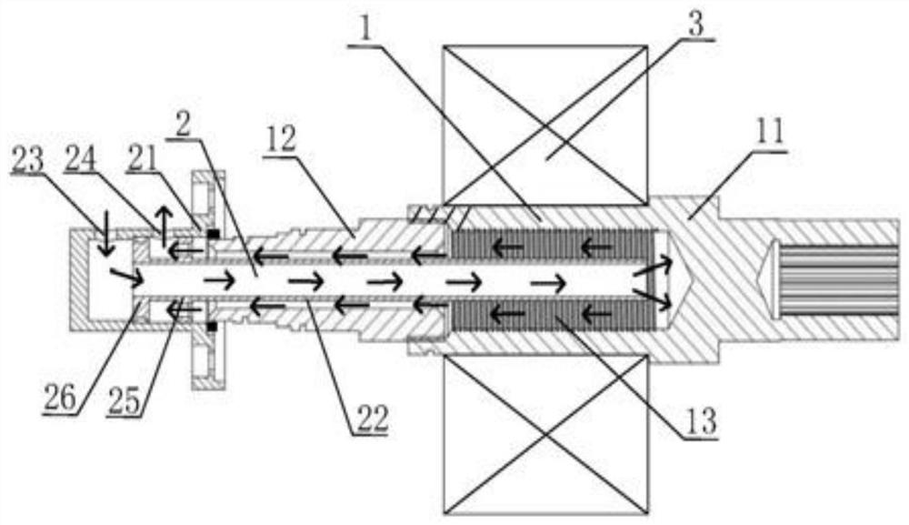
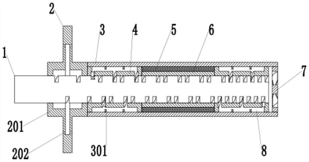
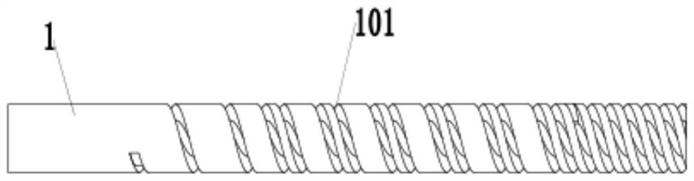
[0025] like Figure 2-5 As shown, an air-floating rotor heat dissipation structure includes a shaft center 1, a thrust plate 2, a sheath 3, a gas delivery device 4 and an impeller 7, and the thrust plate 2 and the sheath 3 are set on the outside of the shaft center 1 , the thrust plate 2 is docked with the sheath 3, and the end of the sheath 3 away from the thrust plate 2 is provided with an impeller 7, and the inside of the sheath 3 is provided with a magnetically conductive ring 6 that is sleeved on the outside of the shaft center 1. The outside of the magnetic ring 6 is covered with a magnetic steel 5, and the two sides of the magnetic steel 5 are provided with a gas delivery device 4 sleeved outside the shaft 1, and the side wall of the shaft 1 is provided with a spiral air channel 101, The side wall of the thrust plate 2 is provided with an orifice 202 communicating with the spiral air passage 101 , and the side wall of the sheath 3 is provided with an air hole 301 commun...

Embodiment 2

[0027] like Figure 2-5 As shown, an air-floating rotor heat dissipation structure includes a shaft center 1, a thrust plate 2, a sheath 3, a gas delivery device 4 and an impeller 7, and the thrust plate 2 and the sheath 3 are set on the outside of the shaft center 1 , the thrust plate 2 is docked with the sheath 3, and the end of the sheath 3 away from the thrust plate 2 is provided with an impeller 7, and the inside of the sheath 3 is provided with a magnetically conductive ring 6 that is sleeved on the outside of the shaft center 1. The outside of the magnetic ring 6 is covered with a magnetic steel 5, and the two sides of the magnetic steel 5 are provided with a gas delivery device 4 sleeved outside the shaft 1, and the side wall of the shaft 1 is provided with a spiral air channel 101, The side wall of the thrust plate 2 is provided with an orifice 202 communicating with the spiral air passage 101 , and the side wall of the sheath 3 is provided with an air hole 301 commun...

Embodiment 3

[0036] like Figure 2-5 As shown, a motor includes the heat dissipation structure of the air-floating rotor. The impeller 7 is in interference fit with the sheath 3. The impeller 7 and the sheath 3 can also be fixed together by welding. When the rotor rotates, it can move toward the rotor. High-pressure gas is pumped inside.

[0037] The high-pressure gas pumped by the impeller 7 is transported to each part through the spiral flow channel of the shaft center 1, and at least two flow channels flow through the motor rotor to take away the heat generated in the motor rotor.

[0038] The rear radial bearing gas output device is located between the sheath 3 and the shaft center 1, corresponding to the air hole 301. The part has at least one spiral groove, which can correspond to the spiral flow channel on the shaft center 1, and form an air flow with the corresponding spiral flow channel Channel, this part has an interference fit with the axis 1 to ensure that only the gas in the ...


PUM

PropertyMeasurementUnit
Diameteraaaaaaaaaa

Abstract

The invention discloses an air floatation rotor heat dissipation structure and a motor. The heat dissipation structure comprises an axis, a thrust disc, a sheath, a gas conveying device and an impeller, the thrust disc and the sheath are arranged outside the axis in a sleeving mode, the thrust disc is in butt joint with the sheath, the impeller is arranged at the end, away from the thrust disc, of the sheath, and a magnetic conductive ring arranged outside the axis in a sleeving mode is arranged in the sheath. The magnetic conductive ring is sleeved with magnetic steel, gas conveying devices arranged outside the axis in a sleeving mode are arranged on the two sides of the magnetic steel, a spiral gas channel is formed in the side wall of the axis, a throttling hole communicated with the spiral gas channel is formed in the side wall of the thrust plate, and a gas hole communicated with the spiral gas channel is formed in the side wall of the sheath. The temperature rise problem of the high-speed permanent magnet rotor and a dynamic pressure gas bearing is effectively solved, the problem that high-temperature large current of the high-speed permanent magnet motor is easy to demagnetize is effectively solved, and the reliability of the permanent magnet motor rotor is improved; and the air bearing-rotor does not need an external air source, is more convenient to install and use, and is not influenced by an external air source.

Description

technical field [0001] The invention relates to the technical field of rotor heat dissipation, in particular to an air-floating rotor heat dissipation structure and a motor. Background technique [0002] Elastic foil gas dynamic pressure bearing is a special bearing with high speed, high running accuracy, low loss and high temperature resistance. Among them, the elastic foil gas dynamic pressure bearing is composed of radial elastic foil gas dynamic pressure bearing and axial elastic foil gas dynamic pressure bearing. The radial bearing is mainly composed of top foil, arch foil, bearing seat and other parts. The bearing is composed of top foil, arch foil, bearing seat and thrust bearing. This kind of axial foil bearing also has the problem of high take-off speed and low bearing capacity, and the heat of the bearing and the rotor cannot be dissipated quickly when the rotor is running at ultra-high speed, resulting in the problem that the starting and stopping life of the bea...

Claims


Application Information

Patent Timeline
IPC IPC(8): H02K1/32H02K9/06H02K1/27H02K7/08F16C3/02F16C37/00
CPCH02K1/32H02K9/06H02K1/27H02K7/083F16C3/02F16C37/00
Inventor 刘鹏辉贾金信刘佳佳苏久展闫瑾陈振
Owner GREE ELECTRIC APPLIANCES INC OF ZHUHAI
Why Eureka
Try Eureka