Triggering vibration real-time correction circuit and method in random sampling process

A technology of triggering jitter and real-time correction, applied in electrical components, pulse processing, pulse technology, etc., can solve the problems of nonlinear error of double-slope widening circuit, expansion multiple affecting interpolation time accuracy, increasing circuit board volume, etc.

Active Publication Date: 2014-02-12
CHINA ELECTRONIS TECH INSTR CO LTD
View PDF4 Cites 21 Cited by
  • Summary
  • Abstract
  • Description
  • Claims
  • Application Information

AI Technical Summary

Problems solved by technology

[0004] The disadvantages of adopting the prior art are: 1, the interpolation time discrimination circuit uses a plurality of ECL level D flip-flops, the cost is high, the power consumption is large, causes serious heating, and inc

Method used


Image

  • Triggering vibration real-time correction circuit and method in random sampling process
  • Triggering vibration real-time correction circuit and method in random sampling process

Examples


Embodiment 1

[0013] Such as Figure 1-2 As shown, in the pulse power measurement, in the random sampling process, since the signal under test is arbitrary, the trigger signal synchronous with the signal under test is also arbitrary, and the trigger signal is not related to the sampling clock, so the trigger signal and the trigger point after The time interval between the first sampling clocks of , causes trigger jitter, which is a uniformly distributed and bounded random variable. The key to random sampling is to calculate the time interval between the trigger point and the sampling point, so as to determine the exact position of the sampling point on the screen.

[0014] The technical problems to be solved by the present invention include: 1. Design of a digital precision interpolation identification circuit; 2. Optimal design of a double-slope expansion circuit; 3. Precision interpolation time calibration technology.

[0015] Design of hardware circuit

[0016] Such as figure 1 As sho...

Embodiment 2

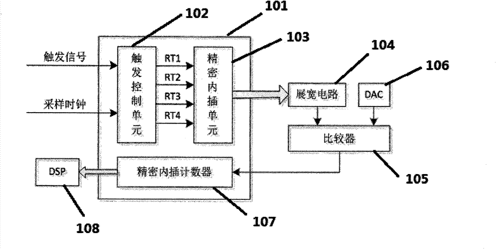
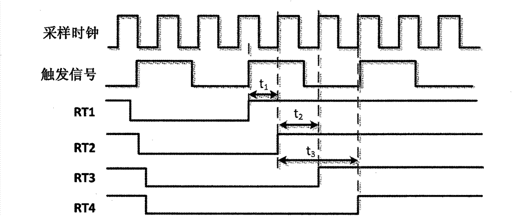
[0034] On the basis of the above examples, if Figure 1-2 As shown, a trigger jitter real-time correction circuit in the random sampling process, wherein the trigger signal and sampling clock settings are connected to the trigger control unit 102 in the editable logic unit FPGA101, and the trigger control unit 102 generates four-way timing After the signal is set, it is connected to the precision interpolation unit 103 in the editable logic unit 101, and the time interval t between the rising edge of the trigger signal and the rising edge of the first sampling clock thereafter is 1 , the time interval t of one sampling clock cycle 2 , or the time interval t between two sampling periods 3 Go to the stretching circuit 104 and the comparator 105, and then set it to be connected with the precision interpolation counter 107 in the editable logic unit 101, and then input the count value to the digital signal processor DSP108 for calculating the precision interpolation time interval...


PUM


Abstract

The invention provides a triggering vibration real-time correction circuit and method in a random sampling process. A triggering signal and sampling clocks are set to be connected with a triggering control unit in a programmable logic unit, and then set to be connected with a precise inserted-in unit in the programmable logic unit after four ways of sequence signals are generated, the time interval t1 between the rising edge of the triggering signal and the rising edge of the next first sampling clock or the time interval t2 of one sampling clock or the time interval t3 between two sampling cycles is set to a widening circuit or a comparator, and then set to be connected with a precise inserted-in counter in the programmable logic unit, and generated counting values are input to a digital signal processor, the t1 is a precise inserted-in time interval needing to be measured, and the t2 and the t3 are used for correcting the inserted-in time. Through the technical scheme, a digital precise inserted-in time discrimination circuit is achieved inside an FPGA, and triggering vibration is eliminated through the optimization design of a double-slope expander circuit and the correction technology of the inserted-in time.

Description

technical field [0001] The invention belongs to the technical field of pulse power measurement, and in particular relates to a trigger jitter real-time correction circuit method in a random sampling process. Background technique [0002] In pulse power measurement, if real-time sampling is used, a sufficiently high sampling rate is required, and to increase the sampling rate, a high-speed A / D converter must be used, but high-speed A / D and sample memory are expensive. In most cases, the measurement signal is a periodic signal, so in order to obtain a high repetitive signal measurement bandwidth at a lower sampling rate, the system uses random sampling for data acquisition. [0003] At present, for the measurement of the precise interpolation time of the trigger signal and the sampling clock, it is mainly through a series of D flip-flops to generate the precise interpolation time, and after being widened by a double-slope widening circuit, it is shaped by a comparator and coun...

Claims


Application Information

Patent Timeline
IPC IPC(8): H03K5/1252
Inventor 李强李金山冷朋
Owner CHINA ELECTRONIS TECH INSTR CO LTD
Why Eureka
Try Eureka