Data transmission method and device

A data transmission method and equipment technology, applied in the field of data transmission, can solve problems such as mismatching data transmission technology

Inactive Publication Date: 2014-02-12
COMBA TELECOM SYST CHINA LTD
View PDF9 Cites 16 Cited by
  • Summary
  • Abstract
  • Description
  • Claims
  • Application Information

AI Technical Summary

Problems solved by technology

[0006] The embodiment of the present invention provides a data transmission method and device, which are used to solve the problem in the prior

Method used


Image

  • Data transmission method and device
  • Data transmission method and device
  • Data transmission method and device

Examples


Embodiment 1

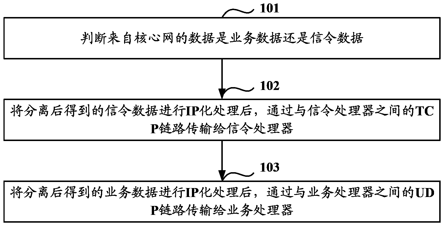
[0034] Such as figure 1 As shown, it is a schematic flow chart of a data transmission method in Embodiment 1, the method includes:

[0035] Step 101: Determine whether the data from the core network is service data or signaling data.

[0036] In step 101, since the data transmission protocols supported by the core network are different, after receiving the data sent by the core network through the data interface of the core network, the received data is converted into the same recognizable format, and the converted data is separated , to separate signaling data and service data.

[0037] It should be noted that the signaling data may be SS7 signaling data.

[0038] Step 102: After performing IP processing on the separated signaling data, transmit it to the signaling processor through the TCP link with the signaling processor.

[0039] In this step 102, IP processing is performed on the signaling data obtained after separation, specifically including:

[0040] Step 1: Decod...

Embodiment 2

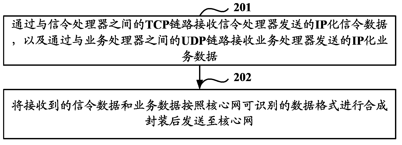
[0071] Such as figure 2 As shown, it is a schematic flowchart of a data transmission method in the second embodiment. The second embodiment is the reverse process of the data transmission method of the first embodiment, and the method includes:

[0072] Step 201: Receive the IP-based signaling data sent by the signaling processor through the TCP link with the signaling processor, and receive the IP-based service data sent by the service processor through the UDP link with the service processor .

[0073] Wherein, the IP-based signaling data sent by the signaling processor is received through the TCP link with the signaling processor, specifically including:

[0074] Step 1: Receive the TCP data sent by the signaling processor through the TCP link for downlink transmission of signaling data.

[0075] It should be noted that the signaling data for uplink transmission and the signaling data for downlink transmission use the same TCP link.

[0076] Step 2: Decoding the receiv...

Embodiment 3

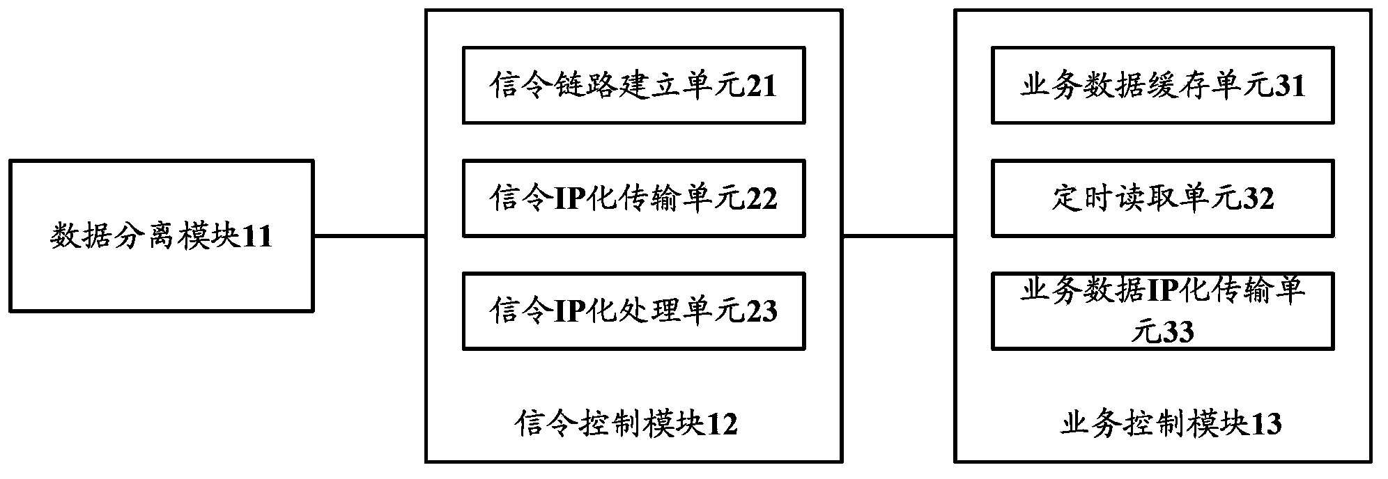
[0088] Such as image 3 As shown, it is a schematic structural diagram of a data transmission device in the third embodiment, the device includes: a data separation module 11, a signaling control module 12 and a service control module 13, wherein:

[0089] Data separation module 11, for judging whether the data from the core network is service data or signaling data;

[0090] The signaling control module 12 is used to transfer the signaling data to the signaling processor through the TCP link with the signaling processor after IP conversion of the signaling data when the data separation module judges that the data is signaling data;

[0091] The service control module 13 is configured to convert the service data into IP and transmit the service data to the service processor through the UDP link with the service processor when the data separation module judges that the data is service data.

[0092] Specifically, the signaling control module 12 specifically includes: a signali...


PUM


Abstract

The invention discloses a data transmission method and device. The data transmission method and device are characterized in that received data are separated into signaling data and service data, IP processing is carried out on the separation signaling data, then the signaling data are transmitted to a signaling processor through a TCP link between the data transmission device and the signaling processor, IP processing is carried out on the separation service data, then the service data are transmitted to a service processor through a UDP line between the data transmission device and the service processor, and therefore the problem that in the prior art, the IP data transmission technology used in a base station is not matched with the data transmission technology supported by the core network is solved.

Description

technical field [0001] The present invention relates to the communication field, in particular to a data transmission method and equipment. Background technique [0002] With the development of wireless communication technology, the R5 version released by the 3GPP (The 3rd Generation Partnership Project) standardization organization introduces IP UTRAN (Internet Protocol Universal Terrestrial Radio Access Network, between networks) into the access network. Interconnection protocol Terrestrial Wireless Access Network) and HSDPA (High Speed ​​Downlink Packet Access, high-speed downlink packet access), in which IP is used as the signaling transmission and user data bearer of UTRAN, and HSDPA supports high-speed downlink packet data access technology, making The data transmission between RNC (Radio Net Control, radio network controller) and Node B in the base station transmission system realizes IP transmission. Compared with the previous R4 version that uses E1 link for data t...

Claims


Application Information

Patent Timeline
IPC IPC(8): H04L29/06H04W28/06H04W80/04H04W80/06H04W88/14
Inventor 唐宽
Owner COMBA TELECOM SYST CHINA LTD
Why Eureka
Try Eureka