
Machining device for machining polygon and machining method thereof

A processing device and polygon technology, applied in metal processing equipment, manufacturing tools, milling machine equipment details, etc., can solve problems such as poor accuracy, low efficiency, and inability to meet the needs of small and medium-sized enterprises, and achieve the effect of ensuring verticality.

Active Publication Date: 2014-02-19
ANHUI HUAXING FIRE EQUIP GRP CO LTD
View PDF7 Cites 4 Cited by
  • Summary
  • Abstract
  • Description
  • Claims
  • Application Information

AI Technical Summary

Problems solved by technology

The traditional processing technology generally uses machine tools such as milling machines, planers or machining centers to process the above structures. However, the efficiency and precision of polygonal workpieces are processed by milling machines and planers, which makes the processed parts unable to meet the requirements of use; Although machining center processing can meet the requirements of precision, the processing cost is quite high and cannot meet the needs of small and medium-sized enterprises, which limits production needs

Method used


Image

  • Machining device for machining polygon and machining method thereof
  • Machining device for machining polygon and machining method thereof
  • Machining device for machining polygon and machining method thereof

Examples


Embodiment Construction

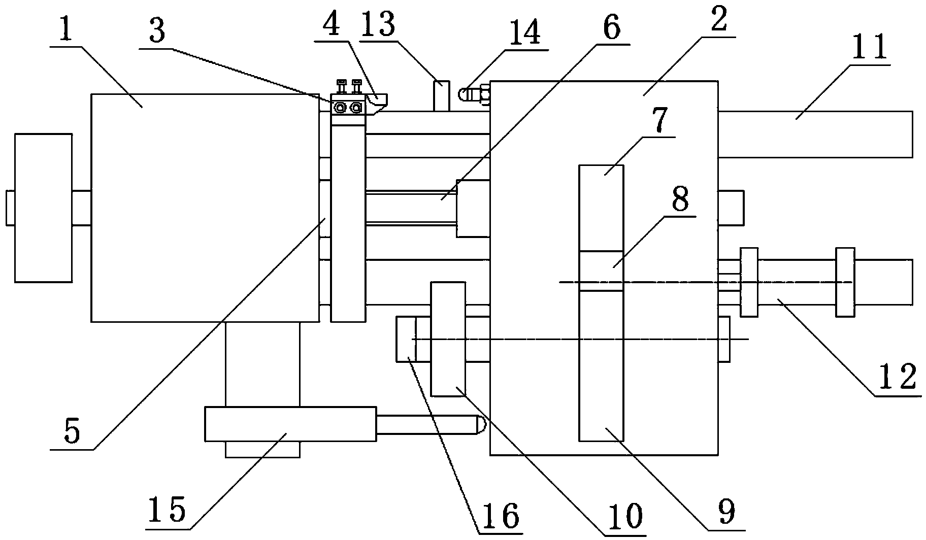
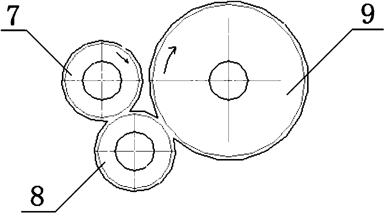
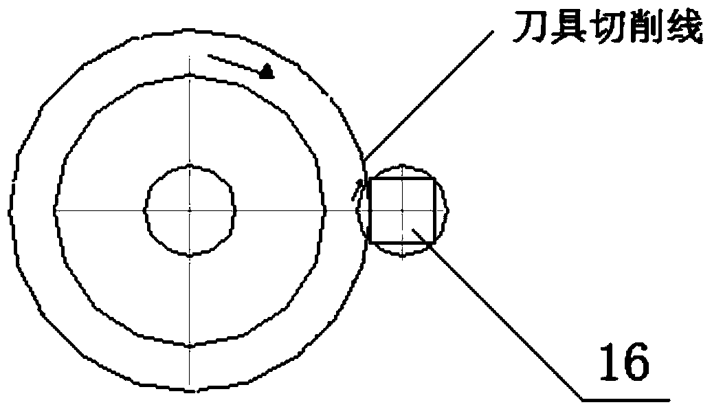
[0022] figure 1 It is a structural schematic diagram of a processing device for processing polygons according to the present invention, figure 2 It is the transmission schematic diagram of the present invention, image 3 It is the cutting schematic diagram of the present invention. Depend on Figure 1-3 Combining the shown structures, it can be seen that this kind of processing device for processing polygons includes a main box 1 and a sub-box 2 arranged side by side. The main box 1 is equipped with a first shaft, and the first shaft is close to the sub-box. One end of the box body 2 is provided with a cutterhead 3, and a cutting tool 4 is installed on the cutterhead 3, which is located on the main box body 1 and is close to one end of the auxiliary box body 2, and is provided with a hydraulic pressure that limits the amount of cutting tool 4. Buffer deceleration cylinder 15; one end of the cutterhead 3 on the first shaft is also provided with a spline groove cover 5; the ...


PUM


Abstract

The invention discloses a machining device for machining a polygon and a machining method thereof. The machining device comprises a main box body and an auxiliary box body which are arranged side by side, a first shaft is installed on the first main box, a cutter head is arranged at one end, close to the auxiliary box body, of the first shaft, the cutter head is provided with a cutting tool, and the end, where the cutter head is arranged, of the first shaft is further provided with a spline groove sleeve; a second shaft is installed on the auxiliary box body, a spline groove is formed in one end, close to the main box body, of the second shaft, the spline groove is matched with the spline groove sleeve in installation, a driving wheel is installed on a position, located inside the auxiliary box body, of the second shaft, and the common multiple of the ratio of the number of teeth of the driving wheel to the number of teeth of a driven wheel is equal to the number of sides of the polygon to be machined; the driven wheel transmits power to a driven wheel installed on a third shaft through a middle idle gear, and a chuck is installed at the end, close to the main box body, of the third shaft. The machining device can achieve one-time machining forming for polygon components, and compared with working efficiency of an existing milling machine and a planning machine, working efficiency of the machining device can be increased by 2-3 times.

Description

technical field [0001] The invention relates to a processing device for processing polygons and a processing method thereof. Background technique [0002] In the machining process, there are often many cylinders or structures with the following shapes on one end of the screw: diagonals, isosceles triangles, squares, hexagons and other parts. The traditional processing technology generally uses machine tools such as milling machines, planers or machining centers to process the above structures. However, the efficiency and precision of polygonal workpieces are processed by milling machines and planers, which makes the processed parts unable to meet the requirements of use; Although the processing of machining centers can meet the requirements of precision, the processing cost is quite high, which cannot meet the needs of small and medium-sized enterprises, which limits the production needs. Contents of the invention [0003] The technical problem to be solved by the present...

Claims


Application Information

Patent Timeline
Patent Type & Authority Applications(China)
IPC IPC(8): B23P15/00
CPCB23C3/24
Inventor 王次财奚军王飞奚正玉
Owner ANHUI HUAXING FIRE EQUIP GRP CO LTD
Learn More