Swing material-hooking device

A hooking and swinging cylinder technology, applied in the field of profile positioning devices, can solve problems such as inability to accurately reach the clamping position, inability to complete the profile clamping function, and non-fixation, so as to achieve stable and smooth feeding process, convenient adjustment and control, and positioning high precision effect

Active Publication Date: 2014-02-19
济南天辰智能装备股份有限公司
View PDF5 Cites 4 Cited by
  • Summary
  • Abstract
  • Description
  • Claims
  • Application Information

AI Technical Summary

Problems solved by technology

[0003] In the door, window and curtain wall processing equipment with a high degree of automation, the profile feeding device (refer to Figure 4 ) is often conveyed by a conveyor belt, that is, the feeding synchronous belt 26 of the conveying device on the storage rack 24 transmits the profile 21 to be processed to the horizontal support roller 22, and then the CNC clamping manipulator clamps the end face of the profile 21 on the horizontal support roller 22 moves up to realize the feeding movement. Since the profile 21 cannot interfere with the conveyor belt during the movement, it is determined that there must be a distance difference between the conveyor belt and the supporting rollers. Therefore, the profile cannot be completely separated from the conveyor belt only by the transmission of the conveyor belt, resulting in The transmission position of the profile from the synchronous belt to the horizontal support roller is relatively free, uncertain and not fixed, and cannot accurately reach the corresponding clamping position of the manipulator, so that the clamping manipulator cannot complete the profile clamping function

Method used


Image

  • Swing material-hooking device
  • Swing material-hooking device
  • Swing material-hooking device

Examples


Embodiment Construction

[0019] The present invention will be further described below through non-limiting embodiments and in conjunction with the accompanying drawings.

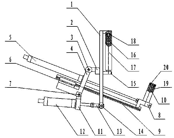
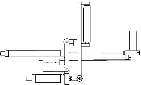
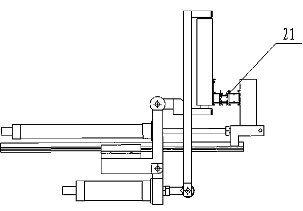
[0020] Figure 1 to Figure 4 It is a schematic diagram of a specific embodiment of the present invention, including a frame 23 and a beam 25 fixed on the frame 23, a horizontal support roller 22 is fixed on the beam 25, and a vertical vertical plate 1 is connected to the beam 25 , the middle part of the vertical vertical plate 1 is fixed with a hinge shaft seat 2, the bottom of the vertical vertical plate 1 is hinged with the rod end of the swing cylinder 12, the cylinder seat of the swing cylinder 12 is hinged at one end of the support seat 4, and the other end of the support seat 4 It is hinged with the hinge shaft seat 2; the support seat 4 is fixed with a material hook cylinder 5, and the rod end of the material hook cylinder 5 is rotatably connected with a material hook roller 19.

[0021] In the present invention, the hinge s...


PUM


Abstract

The invention discloses a swing material-hooking device. The swing material-hooking device comprises a rack and a beam fixed to the rack; a horizontal material supporting roller is fixed to the beam, a vertical plate is connected to the beam, a hinged shaft base is fixed to the middle of the vertical plate, the lower portion of the vertical plate is hinged to the rod end of a swing air cylinder, an air cylinder base of the swing air cylinder is hinged to one end of a supporting seat, and the other end of the supporting seat is hinged to the hinged shaft base; a material hooking air cylinder is fixed to the supporting seat, and the rod end of the material hooking air cylinder is rotationally connected with a material hooking roller. In the loading process of section bars, the material hooking roller is raised in a swing mode through a connecting rod structure, the rod end of the material hooking air cylinder retracts and can drive the material hooking roller to move to a side roller, so that the section bars are clamped between the material hooking roller and the side roller, and the positioning accuracy is high; moreover, bearings are inlaid into the side roller and the material hooking roller respectively, the side roller and the material hooking roller can roll in the conveying process of the section bars, friction force in the conveying process is reduced, and the swing material-hooking device is simple and compact in structure, stable and smooth in whole loading process and convenient to adjust and control.

Description

[0001] technical field [0002] The invention relates to the technical field of door and window profile processing equipment, in particular to a profile positioning device on the door and window profile processing equipment. Background technique [0003] In the door, window and curtain wall processing equipment with a high degree of automation, the profile feeding device (refer to Figure 4 ) is often conveyed by a conveyor belt, that is, the feeding synchronous belt 26 of the conveying device on the storage rack 24 transmits the profile 21 to be processed to the horizontal support roller 22, and then the CNC clamping manipulator clamps the end face of the profile 21 on the horizontal support roller 22 moves up to realize the feeding movement. Since the profile 21 cannot interfere with the conveyor belt during the movement, it is determined that there must be a distance difference between the conveyor belt and the supporting rollers. Therefore, the profile cannot be completel...

Claims


Application Information

Patent Timeline
Patent Type & Authority Applications(China)
IPC IPC(8): B23Q7/00B23Q7/04
CPCB23Q7/00
Inventor 孟令芝张修福郭宁
Owner 济南天辰智能装备股份有限公司
Why Eureka
Try Eureka