Method for sucking printing ink, printing device, and print head for same and

A printing device and printing ink technology, used in packaging, printing, typewriters, etc., can solve problems such as the reduction of the quality of printed images, and achieve the effect of small mechanical pollution and high printing quality.

Active Publication Date: 2014-02-19
KRONES AG
View PDF9 Cites 2 Cited by
  • Summary
  • Abstract
  • Description
  • Claims
  • Application Information

AI Technical Summary

Problems solved by technology

The upward suction requires a sufficient volume flow of the suction device, however it cannot be prevented that a part of the printing ink is dragged upwards before it impinges on the printing area of ​​the container, and in unfa...

Method used


Image

  • Method for sucking printing ink, printing device, and print head for same and
  • Method for sucking printing ink, printing device, and print head for same and
  • Method for sucking printing ink, printing device, and print head for same and

Examples


Embodiment Construction

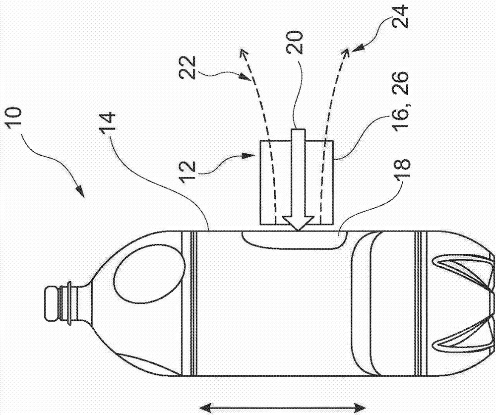
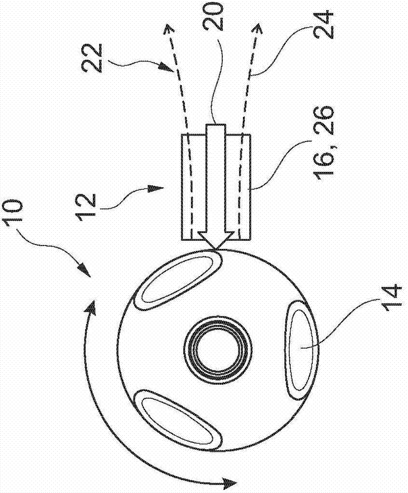
[0034] The two schematic views of FIG. 1 show a plastic container 10 which has been printed on its outer surface 14 by means of a printing device 12 according to the invention in a direct printing method. The plastic container 10 may especially be a PET container, as it is widely used in the beverage industry. After printing, the container 10 can be filled with a liquid, such as a beverage, in a downstream filling station and then closed hermetically at the opening on its top side. The printing device 12 comprises at least one printing head 16 which is at least during the printing process in a defined relative position with respect to the printing area 18 on the container surface 14 and which is prepared to apply liquid printing ink 20 to the container 10 or on the bottle. After the container 10 has been printed, the printing ink 20 applied in the printing zone 18 can be cured, for example by means of UV curing, by means of heat or by other suitable measures. This curing (no...


PUM


Abstract

The invention relates to a printing device used for printing commodities. The printing device comprising a printing head in a defined relative position relative to a printing area on the outer surface of an article or container at least in a printing process, in connection with a sucking device used for sucking sprayed and/or spattered printing ink. The extraction device is spatially and functionally associated with the printing head. The invention further relates to a method for sucking sprayed and/or spattered ink in the vicinity of an exit openings for printing ink of the printing head. The printing head is configured for applying liquid ink to a printing area of an article, a containter, or a bottle or the like, and in a defined relative position relative to a printing area on the outer surface of an article or container at least in a printing process.

Description

technical field [0001] The invention relates to a printing device. Furthermore, the invention relates to a method for suctioning sprayed and / or ejected printing ink in the region of a print head. Background technique [0002] Furthermore, printing devices for printing goods, such as containers or bottles, are known as so-called direct printing devices, which generally comprise at least one electronically or digitally actuatable print head, by means of which goods, containers or bottles can be printed. In this case, the at least one print head is in a defined relative position relative to the printing area on the outer surface of the good or the outer surface of the container at least during the printing process, so that the defined printing area can be loaded with printing fluid, printing ink or ink . Such a direct printing method can replace labelling, as the printed area forms a design feature that appears similar to a conventional label including ingredient content, and...

Claims


Application Information

Patent Timeline
IPC IPC(8): B41J3/407B65B61/02
CPCB41J2/1714B41J3/4073B41J3/40733
Inventor 托马斯·费舍尔安德烈亚斯·克劳斯安德烈亚斯·松瑙尔奥古斯特·珀于特
Owner KRONES AG
Why Eureka
Try Eureka