Floating side plate for high-pressure large-displacement gear pump

A floating side plate, large displacement technology, applied in pump components, machines/engines, rotary piston type/oscillating piston type pump components, etc. Unbalance and other problems, to achieve the effect of improving the stress condition, the symmetrical flow field distribution, and the improvement of the pressure gradient

Inactive Publication Date: 2014-02-19
TONGJI UNIV
View PDF6 Cites 5 Cited by
  • Summary
  • Abstract
  • Description
  • Claims
  • Application Information

AI Technical Summary

Problems solved by technology

[0004] Although the gear pump with symmetrical floating side plate structure as the axial sealing method has been finalized and produced for many years, the existing high-pressure and large-displacement fully hydraulic floating side plate gear pump still generally has radial pressure that is difficult to balance and side plates are unevenly stressed. , Torque unbalance leads to problems such as wear and tear, these conditions seriously restrict the performance of the gear pump
In summary, the unbalanced torque of the symmetrical side plate with full hydraulic compensation leads to serious wear on the end face of the side plate gear

Method used


Image

  • Floating side plate for high-pressure large-displacement gear pump
  • Floating side plate for high-pressure large-displacement gear pump
  • Floating side plate for high-pressure large-displacement gear pump

Examples


Embodiment Construction

[0021] The present invention will be further described below in conjunction with the embodiments shown in the accompanying drawings.

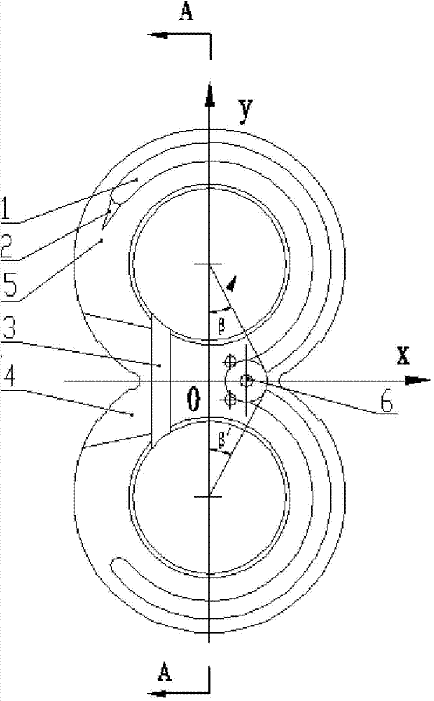
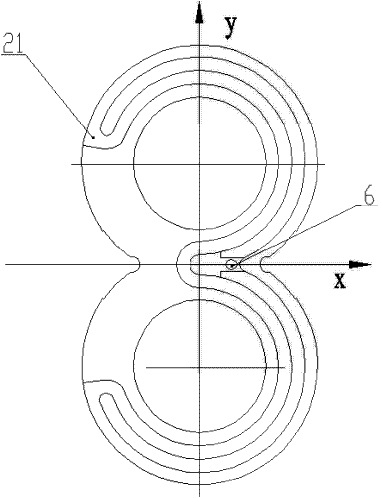
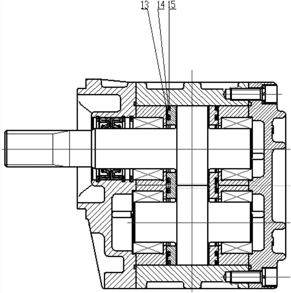
[0022] like figure 1 and figure 2 A floating side plate for a high-pressure large-displacement gear pump is shown, including a side plate body, an unloading groove 3 provided on the reverse thrust surface of the side plate body, an oil hole 7, a driving gear shaft hole and a driven gear The shaft hole and the compensation force groove 15 arranged on the compensation surface of the floating side plate are also provided with an ear-shaped high-pressure oil tank 1 on the reverse thrust surface of the floating side plate. A set of arc-shaped grooves, the central inflection point of the joint of the two sets of arc-shaped grooves is set concentrically with the oil hole 6, and communicated with the oil hole 6, both ends of the arc-shaped groove are located on the side of the oil suction chamber, so that the high pressure area Expand to the side of...


PUM


Abstract

The invention discloses a novel asymmetric floating side plate for a high-pressure large-displacement external-engaged gear pump. The novel asymmetric floating side plate comprises a side plate body, an unloading groove, an oil hole, a driving gear shaft hole, a driven gear shaft hole and a balancing force groove, wherein the unloading groove, the oil hole, the driving gear shaft hole and the driven gear shaft hole are formed in a reverse thrust surface of the side plate body; the balancing force groove is arranged in the balancing surface of the floating side plate; the reverse thrust surface of the floating side plate is also provided with an ear-shaped high-pressure oil groove; the ear-shaped high-pressure oil groove comprises two groups of arc-shaped grooves which are symmetric by taking a horizontal cross shaft as the center; and the tail end of the arc-shaped groove located at a driving gear side is also provided with a damping groove structure located in a transition region. A high-pressure region (oil discharging cavity) on the reverse thrust surface of the floating side plate is enlarged to the side of a low-pressure region (oil suction cavity) of the side plate in a way of excessively opening a w-shaped high-pressure oil groove, so that a gear shaft is balanced, and the radial force of a bearing is reduced; and meanwhile, the tail end of the high-pressure oil groove at a driving gear side is provided with the V-shaped damping groove structure, so that the pressure distribution on the surface of a reverse thrust surface side of the side plate is improved, the symmetric distribution of pressures at the driving gear side and the driven gear side of the reverse thrust surface of the floating side plate is realized, and finally, the force balance of the floating side plate is realized.

Description

technical field [0001] The invention belongs to a component of an external meshing gear pump, in particular to a floating side plate. Background technique [0002] Because of its simple structure, small size, light weight, strong self-priming ability, and insensitivity to oil pollution, gear pumps are widely used in the field of hydraulic technology, especially in the engineering machinery industry. At present, in the field of construction machinery, domestic and foreign OEMs (such as loaders, bulldozers, etc.) have higher and higher requirements for the displacement, pressure level and service life of gear pumps, and the wear of gear pump side plates has become a constraint for gear pump discharge. A key factor in increasing volume and increasing pressure levels. [0003] The central sealed gear pump adopts the "8" shaped compensation symmetrical structure floating side plate on the axial seal (see figure 1 ), that is, the full hydraulic compensation symmetrical side plat...

Claims


Application Information

Patent Timeline
Patent Type & Authority Applications(China)
IPC IPC(8): F04C15/00
Inventor 王安麟刘巍张小路单学文姜涛
Owner TONGJI UNIV
Why Eureka
Try Eureka