Dynamic-static pressure lubricating type flow distribution plate

A flow plate, dynamic and static pressure technology, applied in the field of hydraulic components, can solve the problems affecting the reliability and service life of the plunger pump, increase leakage and other problems, achieve the effect of long arm, reduce leakage and enhance the effect

Active Publication Date: 2015-07-15
ZHEJIANG UNIV OF TECH
View PDF5 Cites 6 Cited by
  • Summary
  • Abstract
  • Description
  • Claims
  • Application Information

AI Technical Summary

Problems solved by technology

At present, the development of high-speed and high-pressure plunger pumps is being severely restricted by the lubrication and sealing characteristics of the flow distribution pair, which greatly affects the reliability and service life of the plunger pump. Many studies have analyzed the large pressure difference between the suction and discharge ports and the distribution plate. Slotted holes are provided to reduce cavitation and vibration noise, but rarely cause increased leakage problems

Method used


Image

  • Dynamic-static pressure lubricating type flow distribution plate
  • Dynamic-static pressure lubricating type flow distribution plate
  • Dynamic-static pressure lubricating type flow distribution plate

Examples


Embodiment 1

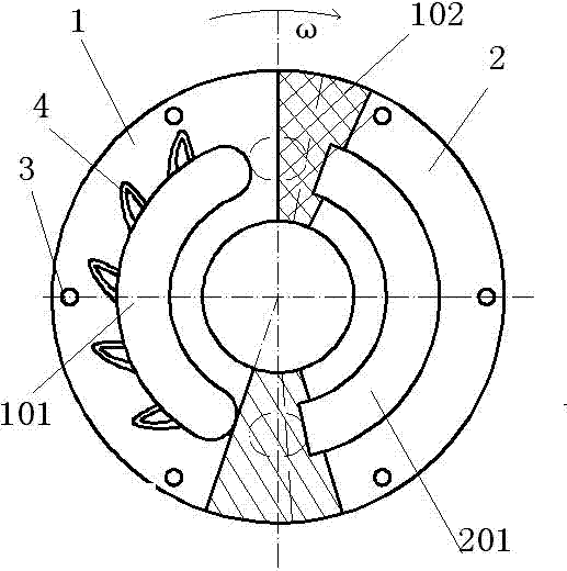
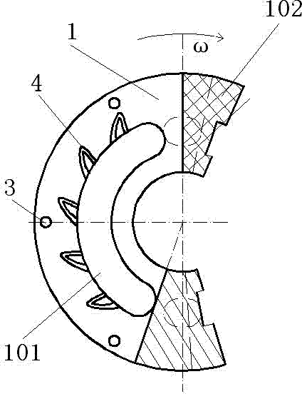
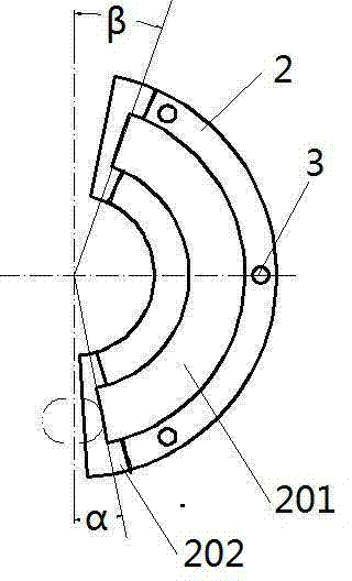
[0016] Embodiment 1: A dynamic and static pressure lubricated distribution plate, which is disc-shaped as a whole, see figure 1 , including a waist-shaped high-pressure oil discharge port 101 on one side, a waist-shaped low-pressure oil suction port 201 isolated from the former on the other side, and an installation positioning hole 3 near the outer peripheral side. The plunger pump flow plate is divided into blocks by oil discharge 1 and the oil-absorbing block 2 are spliced ​​together, and the oil-discharging block 1, see figure 2 , greater than oil-absorbing block 2, see image 3 and Figure 4 , the splicing positions are respectively located at the beginning and end edges of the waist-shaped low-pressure oil suction port 201, and the upper joint 102 of the oil discharge block 1 is overlapped above the lower joint 202 of the oil suction block, and the outer diameter of the plunger pump distribution plate The outer diameter of the end face of the corresponding rotor cylin...

Embodiment 2

[0017] Embodiment 2: The structural principle is the same as that of Embodiment 1, and the difference is that the upper joint 102 of the oil discharge block 1 is overlapped above the lower joint 202 of the oil suction block, and the unloading area of ​​the upper joint 102 of the oil discharge block is a downward slope , the slope is 0.5°, the highest point of the slope starts from the center line of the upper dead zone, and descends to the minimum thickness of the upper joint 103 of the oil discharge block, that is, the lowest point of the lower slope, as shown in the grid area; the oil discharge block The preloading area of ​​the upper joint 103 is an upward slope with a slope of 1°. The lowest point of the slope begins at the minimum thickness of the upper joint of the oil discharge block, and ends at the tangent line of the edge line at the beginning of the high-pressure oil discharge port, that is, the highest point of the upper slope. See The hatched area in the figure. T...

Embodiment 3

[0019] Embodiment 3: The structural principle is the same as that of Embodiment 2, the upper joint 102 of the oil discharge block 1 is overlapped above the lower joint 202 of the oil absorption block, and the unloading area of ​​the upper joint 102 of the oil discharge block is a downward slope with a slope of - 0.5°, the highest point of the slope starts from the center line of the upper dead zone, and descends to the minimum thickness of the upper joint 103 of the oil discharge block, that is, the lowest point of the lower slope, as shown in the grid area in the figure; the upper joint 103 of the oil discharge block The preloading area of ​​the pump is an upward slope with a slope of 0.5°. The lowest point of the slope starts from the minimum thickness of the upper joint of the oil discharge block, and ends at the tangent line of the edge line at the beginning of the high-pressure oil discharge port, that is, the highest point of the upward slope, as shown in the figure. Slas...


PUM


Abstract

The invention relates to the technical field of a hydraulic element, and particularly relates to a flow distribution plate for a plunger pump. The dynamic-static pressure lubricating type flow distribution plate is of a disc shape entirely, and comprises a waist-shaped high pressure oil discharge outlet at one side, a waist-shaped low pressure oil suction inlet, separated from the high pressure oil discharge outlet, at the other side, and installation locating holes at near peripheral sides; the flow distribution plate for the plunger pump is formed by splicing oil discharge blocks and oil suction blocks; the splicing positions are respectively located at the edges of a beginning end and a tail end of the waist-shaped low pressure oil suction inlet; upper joints of the oil discharge blocks are lap-jointed onto the lower joints of the oil suction blocks; the width of an outer sealing belt is 1.1-1.3 times the inner sealing width; a plurality of Eta-shaped three-dimensional tapered grooves, of which the openings are at the oil discharge outlet, are further formed in outer sealing end faces of the oil discharge blocks. The dynamic-static pressure lubricating type flow distribution plate disclosed by the invention has the characteristics of reasonable layout, and convenience in special treatment processing for particular parts of the flow distribution plate; based on the demand on production of fluid dynamic pressure lubrication, adoption of the flow distribution plate can effectively reduce leakage, decrease flow distribution vibration and noise, and reduce generation of a capsizing moment of a cylinder body.

Description

technical field [0001] The invention relates to the technical field of hydraulic components, in particular to a valve plate for a plunger pump. Background technique [0002] The oil film in the distribution pair of the plunger pump has the characteristics of lubricating and sealing at the same time, that is, it needs to seal the compression chambers of each plunger and provide dynamic and static pressure lubrication for the high rotation of the axial support cylinder. At present, the development of high-speed and high-pressure plunger pumps is being severely restricted by the lubrication and sealing characteristics of the flow distribution pair, which greatly affects the reliability and service life of the plunger pump. Many studies have analyzed the large pressure difference between the suction and discharge ports and the distribution plate. Slots are opened on the top to reduce cavitation and vibration noise, but rarely cause increased leakage. The use of dynamic pressure...

Claims


Application Information

Patent Timeline
Patent Type & Authority Applications(China)
IPC IPC(8): F04B53/00F04B53/18
Inventor 彭旭东马晓明孟祥铠
Owner ZHEJIANG UNIV OF TECH
Why Eureka
Try Eureka