Electromagnetic Flowmeter with Fluid Impedance Measurement

An electromagnetic flowmeter and electromagnetic flow technology, applied in the direction of fluid resistance measurement, application of electromagnetic flowmeter to detect fluid flow, volume/mass flow generated by electromagnetic effects, etc., can solve the problem of difficult to distinguish the change of fluid conductivity, without considering the input of the measuring amplifier Impedance and other issues, to achieve the effect of easy control and monitoring

Inactive Publication Date: 2016-08-17
SHANGHAI UNIV
View PDF12 Cites 0 Cited by
  • Summary
  • Abstract
  • Description
  • Claims
  • Application Information

AI Technical Summary

Problems solved by technology

However, the electrode impedance measurement method proposed in this patent does not consider the fact that the input impedance of the measuring amplifier is much greater than the impedance between the two electrodes, even in the case of electrode pollution or empty pipes
In this way, the electrode impedance measurement method proposed in this patent is actually difficult to distinguish fluid conductivity changes, electrode contamination and empty pipe conditions

Method used


Image

  • Electromagnetic Flowmeter with Fluid Impedance Measurement
  • Electromagnetic Flowmeter with Fluid Impedance Measurement
  • Electromagnetic Flowmeter with Fluid Impedance Measurement

Examples


Embodiment 1

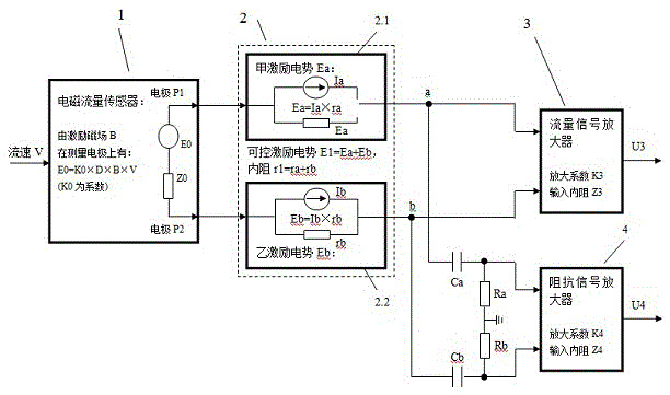
[0024] see figure 1 , the electromagnetic flowmeter with fluid impedance measurement, including: an electromagnetic flow sensor 1 with a pipe diameter D to allow the measured fluid Q to pass through, the electromagnetic flow sensor 1 has an excitation magnetic field B applied to the measured fluid Q, corresponding to the fluid Q The flow velocity V of the electromagnetic flow sensor 1 generates an induced potential E0 =K0×D×B×V whose amplitude is proportional to the flow velocity V between the two measuring electrodes P1 and P2, where K0 is a coefficient; a controllable excitation potential 2 generates a The excitation potential E1 of the internal resistance r1 and the alternating frequency f; the induction potential E0 is connected in series with the excitation potential E1 to form two signal terminals a and b; it is characterized in that the signal terminals a and b are input to a magnification factor K3 A flow signal amplifier 3; the signal terminals a and b are respectivel...

Embodiment 2

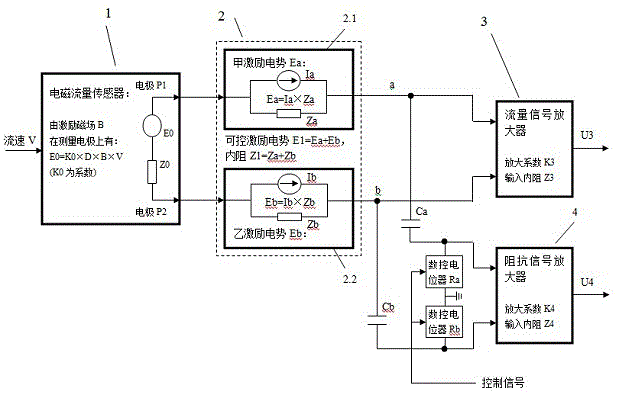
[0035] Embodiment 2: This embodiment is basically the same as Embodiment 1, and the special features are as follows:

[0036] At figure 2 As shown, the resistors Ra and Rb can be implemented with digitally controlled potentiometers, which can be adjusted to the required resistance value according to actual needs, thereby improving the measurement accuracy.

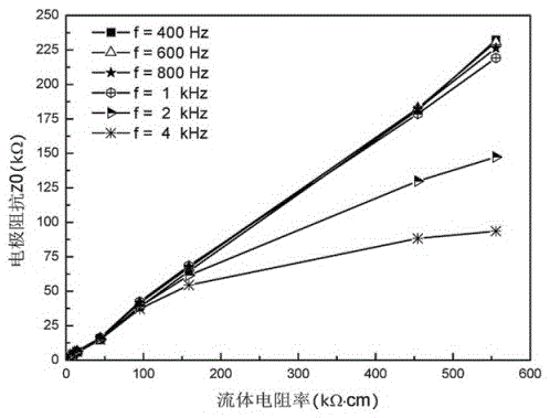
[0037] In this embodiment, the selection of the frequency f of the excitation signal generated by the controllable excitation potential 2 is described.

[0038] The impedance signal amplifier 4 used for electrode impedance measurement is capacitively coupled to the fluid signal measurement circuit. The capacitive reactance presented by the coupling capacitor at the magnetic excitation frequency must be large enough, and the capacitive reactance presented at the alternating frequency f must be relatively large. Small. Therefore, the electric excitation alternating frequency f is generally much larger than the magnetic ex...


PUM


Abstract

The invention provides an electromagnetic flowmeter with fluid impedance measurement. It includes an electromagnetic flowmeter sensor connected to a flow signal amplifier through a controllable excitation potential, and connected to an impedance signal amplifier through two capacitors Ca and Cb; the electromagnetic flowmeter sensor has two electrodes P1 and P2 when there is an excitation magnetic field B There is an induced potential E0 proportional to the fluid flow velocity V on the end, and the induced potential E0 on the electrodes P1 and P2 is connected in series with the excitation potential E1 generated by the controllable excitation potential to form signal terminals a and b; this patent has a flow signal amplifier directly Connect the signal terminals a and b, and measure the fluid flow velocity V when the excitation potential E1=0; at the same time, the impedance signal amplifier is coupled with the signal terminals a and b through two capacitors Ca and Cb, and has an output when the excitation magnetic field B=0 The signal U4 is used to estimate the fluid impedance Z0, that is, the signal U4 can be used to obtain information such as fluid conductivity changes, electrode contamination, and measuring tube empty tubes.

Description

technical field [0001] The invention relates to an electromagnetic flowmeter with fluid impedance measurement, in particular to a dual-excitation electromagnetic flowmeter which uses a photocell-based controllable excitation source to generate an additional AC excitation potential. Conduct electrode impedance measurements. The present invention particularly relates to an electromagnetic flowmeter for measuring the fluid conductivity, detecting the adhesion of the electrode insulation and judging whether the pipe is empty or not according to the measured impedance value of the electrode. technical background [0002] The electromagnetic flowmeter is a measurement equation based on the induced electromotive force generated by the fluid cutting the magnetic field line under the magnetic field excitation state, which is proportional to the flow velocity, and thus forms a measurement system in which the two electrodes of the sensor output the induced potential and the measuring a...

Claims


Application Information

Patent Timeline
Patent Type & Authority Patents(China)
IPC IPC(8): G01F1/58G01R27/22
Inventor 李斌陈洁崔文华徐涛平张欣
Owner SHANGHAI UNIV
Why Eureka
Try Eureka