A test system and method for photoelectric thermal integration of LED devices

A technology for LED devices and testing systems, which is applied in the testing of single semiconductor devices and testing optical performance, etc., can solve the problems of transient thermal resistance error, ignoring the optical power of LED devices, etc., and achieve the effect of improving accuracy

Active Publication Date: 2016-01-13
SHANGHAI UNIV
View PDF5 Cites 0 Cited by
  • Summary
  • Abstract
  • Description
  • Claims
  • Application Information

AI Technical Summary

Problems solved by technology

Due to the current online transient thermal resistance test system, the power used in the data processing process is the heating power directly applied by the test circuit, without considering the optical power emitted by the LED device, and the measured transient thermal resistance has a certain error

Method used


Image

  • A test system and method for photoelectric thermal integration of LED devices
  • A test system and method for photoelectric thermal integration of LED devices
  • A test system and method for photoelectric thermal integration of LED devices

Examples


Embodiment Construction

[0030] The present invention will be further described in detail below in conjunction with the accompanying drawings and specific embodiments.

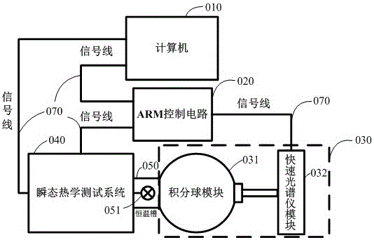
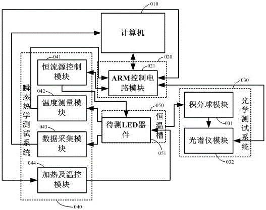
[0031] Such as figure 1 , figure 2 As shown, a test system for photoelectric and thermal integration of LED devices of the present invention includes: a computer (010), an ARM control circuit (020), an optical test system (030), a transient thermal test system (040) and The constant temperature bath (050), the computer (010) are respectively connected to the ARM control circuit (020) and the transient thermal test system (040) through the signal line (070), and the ARM control circuit (020) is respectively connected to the transient thermal test system (040) through the signal line (070). The state thermal test system (040) and the optical test system (030) are connected, and the constant temperature bath (050) is respectively connected with the optical test system (030) and the transient thermal test system (040) through the signal...


PUM


Abstract

The invention discloses a system and method for testing light-electricity-heat integration of an LED device. The system comprises a computer (010), an ARM control circuit (020), an optic testing system (030), a transient thermal testing system (040) and a thermostatic bath (050). The computer (010) is respectively connected with the ARM control circuit (020) and the transient thermal testing system (040) through signal wires (070), the ARM control circuit (020) is respectively connected with the transient thermal testing system (040) and the optic testing system (030) through signal wires (070), and the thermostatic bath (050) is respectively connected with the optic testing system (030) and the transient thermal testing system (040) through signal wires (070). According to the system for testing light-electricity-heat integration of the LED device, optical parameters, electricity parameters and thermal parameters of the LED device are measured at the same time, the luminous power in the measured optical parameters can be adopted, so that electric power exerted by a transient heat resistance testing system on the LED device is corrected, the actual wasted power of the LED device is obtained, and therefore an integration test of light, electricity and heat of the LED device is achieved, and the accuracy of the transient thermal resistance test of the LED device is improved.

Description

technical field [0001] The invention relates to a test system and method for photoelectric and thermal integration of LED devices, which are used for testing the photoelectric and thermal integration of LED devices to be tested. technical background [0002] Solid-state lighting has been used in various fields of life and production because of its many unique advantages compared with previous lighting sources. [0003] Because lighting needs a high-power light source to meet the lighting requirements, power-type solid-state lighting devices, such as LED devices, generate a lot of heat due to the increase in operating current, causing changes in the PN junction temperature of the LED device chip, resulting in forward voltage Dropping changes, color temperature changes, wavelength red shifts, and photoelectric conversion efficiency decreases, which affect the luminosity, chromaticity, and electrical parameters of LED devices. Thermal resistance in electrical parameters is an ...

Claims


Application Information

Patent Timeline
Patent Type & Authority Patents(China)
IPC IPC(8): G01R31/26G01M11/02
Inventor 陈伟杨连乔阙秀福张建华
Owner SHANGHAI UNIV
Why Eureka
Try Eureka