Three element diaphragm damper for fuel pump

A high-pressure fuel pump and diaphragm technology, which is applied to the components, pump components, engine components, etc. of the pumping device for elastic fluids, and can solve the problems of inability to wind up, the diaphragm cannot work, and the pressure of the damper is too large.

Active Publication Date: 2014-02-19
斯塔纳迪恩公司
View PDF8 Cites 17 Cited by
  • Summary
  • Abstract
  • Description
  • Claims
  • Application Information

AI Technical Summary

Problems solved by technology

Second, if excessive pressure pulsations meet each other due to the actuation of the high pressure system overpressure relief valve, the damper will be overstressed to wind up
Finally, when one of the flexible diaphragms does fail, the common gas volume shared by the two diaphragms will be filled with fluid, rendering both diaphragms inoperable

Method used


Image

  • Three element diaphragm damper for fuel pump
  • Three element diaphragm damper for fuel pump
  • Three element diaphragm damper for fuel pump

Examples


Embodiment Construction

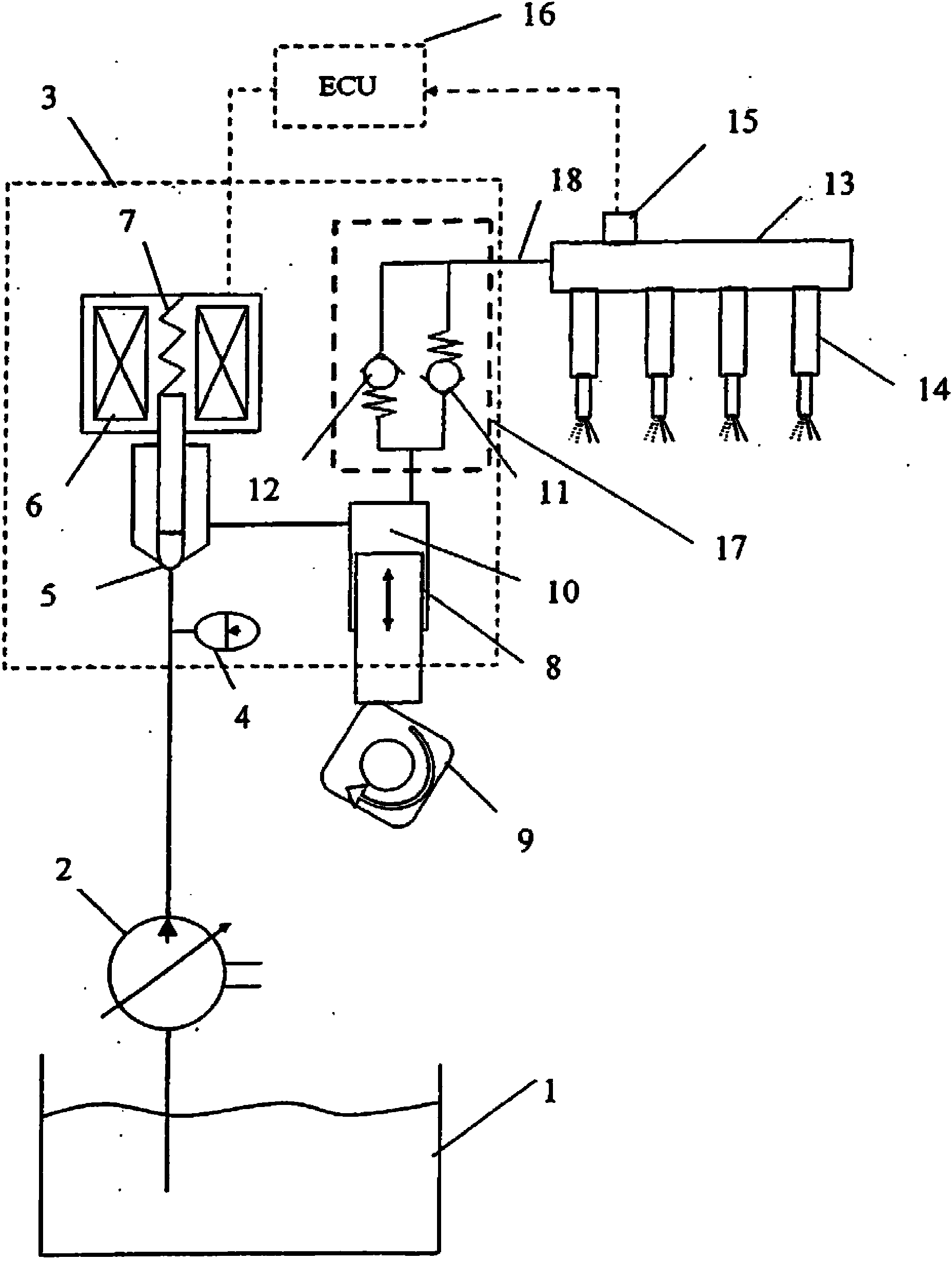
[0024] figure 1 is a schematic diagram illustrating the overall system of an internal combustion engine fuel system. The low pressure pump 2 pressurizes the fuel from the fuel tank 1 and delivers it to the high pressure pump housing 3 through the inlet connection. The fuel then passes through a pressure damper comprising a diaphragm assembly 4 and through a normally closed control valve 5 . In addition, a pressure damper can be located upstream of the pump housing 3 . A normally open control valve is also suitable for this fuel system. The fuel is then pumped into the pump chamber 10 where it is pressurized by the upward movement of the pump piston 8 via the engine camshaft 9 . The control valve 5 acts via a control valve spring 7 and a solenoid 6 to control the amount of fuel delivered by the high pressure pump. This is accomplished by precisely controlling the timing of closing the control valve relative to the upward travel position of the pump piston. When the fuel is...


PUM


Abstract

A damper assembly for a fuel pump includes at least one diaphragm assembly formed by joining two metal diaphragms to respective two sides of an imperforate central plate, thereby creating a pair of closely spaced diaphragms, each acting upon its own gas volume. Preferably, the diaphragm assembly has (a) a rigid, relatively thick circular or polygonal central plate, (b) a first circular diaphragm having a rim portion sealingly secured as by welding to the plate and a relatively thin, flexible, convex portion projecting from one side of the plate and defining a first pressurized gas volume, and (c) a second circular diaphragm having a rim portion sealingly secured as by welding to the plate and a relatively thin, flexible, convex portion projecting from the other side of the plate and defining an independent second pressurized gas volume.

Description

technical field [0001] The present invention relates to a high pressure fuel supply pump, and more particularly to damping pressure pulses resulting from the reciprocating movement of a pump piston which pressurizes fuel to release fuel from the pump. Background technique [0002] Fuel systems for road vehicles are increasingly employing so-called "common rail" configurations whereby the fuel pump maintains a reservoir or "rail" at or above the pressure required for fuel injection and multiple injectors The rail is in fluid communication via respective electronically actuated injection valves, thereby controlling the timing and amount of fuel delivered from the rail to the various cylinders of the engine. The pump typically includes at least one pump piston reciprocated by a cam connection with the engine drive shaft. With the described injection case, the common rail system no longer requires direct synchronization of multiple pump pistons or rotating hydraulic heads. Ins...

Claims


Application Information

Patent Timeline
Patent Type & Authority Applications(China)
IPC IPC(8): F02M69/04
CPCF04B11/00F04B1/0404F04B53/004B23D59/006B27B21/04F04B11/0008F04B43/02F04B53/001
Inventor 罗伯特·G·卢卡斯
Owner 斯塔纳迪恩公司
Why Eureka
Try Eureka