casting shelling machine

A technology of shelling machine and castings, which is applied in the field of shelling machines, can solve the problems of lower casting yield, uncontrollable percussion force, low shelling efficiency, etc., and achieve the effect of increasing yield and moderate vibration

Active Publication Date: 2015-08-26
张家港市天江精密模具制造有限公司
View PDF5 Cites 2 Cited by
  • Summary
  • Abstract
  • Description
  • Claims
  • Application Information

AI Technical Summary

Problems solved by technology

After the casting is formed, the sand on the surface of the casting needs to be crushed to take out the casting. At present, the method of manual hammering is generally used. This method not only has a very low efficiency of shelling, but also uses hard objects to knock it out The force cannot be controlled, and the surface or interior of the casting may be damaged due to excessive knocking, which has a negative impact on the quality of the casting and reduces the yield of the casting.

Method used


Image

  • casting shelling machine

Examples


Embodiment Construction

[0011] The present invention will be described in further detail below through specific examples.

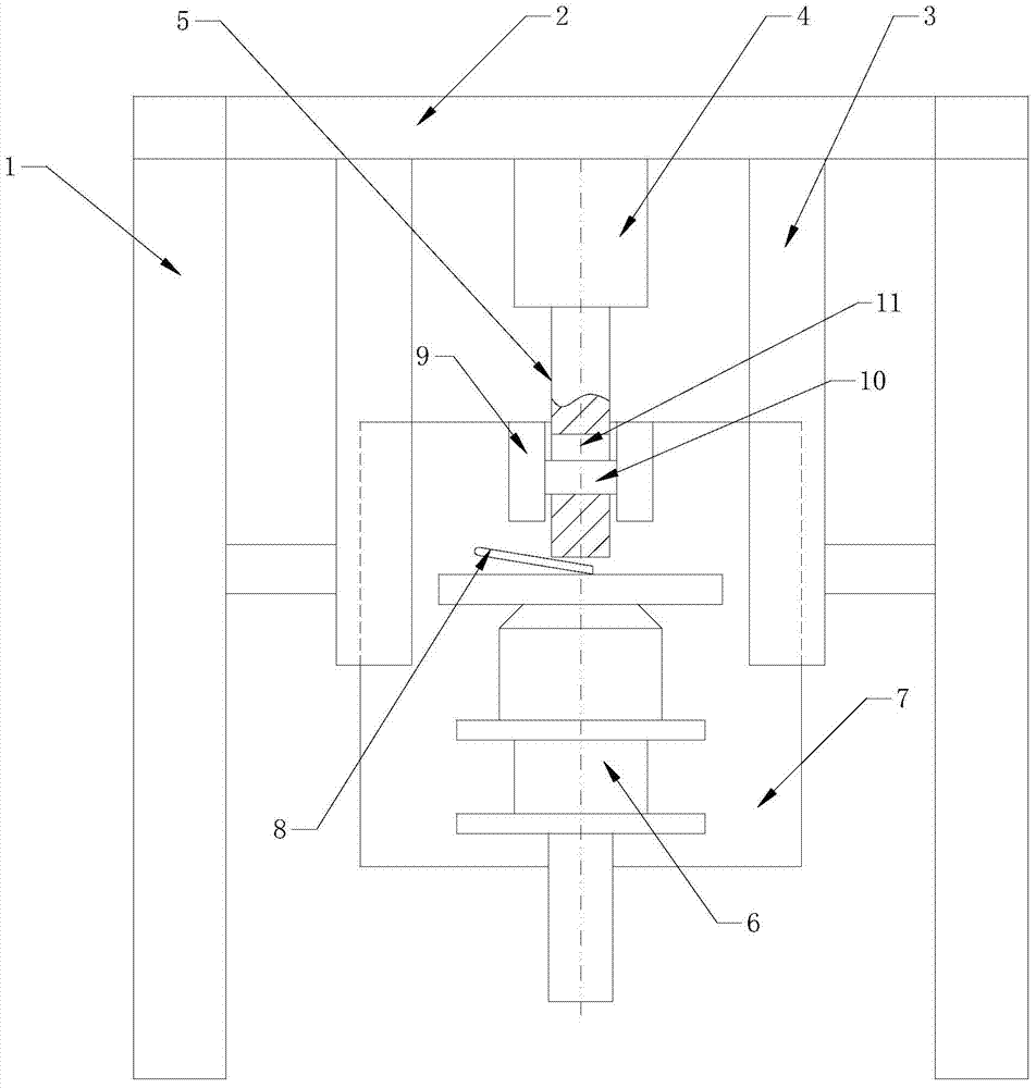
[0012] Such as figure 1 As shown, a casting shelling machine includes a frame, the frame includes a column 1 and an upper beam 2, two vertical guide rails 3 are fixed on the upper beam 2, and a mounting plate 7 is vertically slid on the guide rails 3 The vibrating gun 6 is fixedly installed on the mounting plate 7, the vibrating rod of the vibrating gun 6 is set downwards, the top of the vibrating gun 6 is provided with a contact switch 8 for opening the vibrating gun 6, and the mounting plate 7 is located above the vibrating gun 6 A latch seat 9 is provided, and the latch seat 9 is connected with a vertically provided push rod 5 through a latch 10. The push rod 5 is driven by a power device, and the mounting plate 7 is limited by a limit device to move up and down. The power device is a hydraulic cylinder 4, the cylinder is installed on the upper beam 2 and the piston rod is c...


PUM


Abstract

The invention discloses a casting casing remover comprising a frame. The frame comprises stand columns and an upper cross beam. Two vertical guide rails are fixed on the upper cross beam. A mounting plate is vertically and slidably mounted on the guide rails. A vibrating gun is fixedly mounted on the mounting plate. A vibrating rod of the vibrating gun is arranged downwards. A touch switch for opening the vibrating gun is arranged at the top of the vibrating gun. A plug seat is arranged on the mounting plate and above the vibrating gun, and is connected with a vertical push rod through a plug. The push rod is driven by a power device. Upward and downward movement positions of the mounting plate are limited by a limit device. The casting casing remover can remove casting casings rapidly; dynamic during casing removing is easy to control, so that damage to surfaces or internal structures of castings due to overexertion is avoided, and the rate of finished products is increased.

Description

technical field [0001] The invention relates to a shelling machine, in particular to a casting shelling machine utilizing the principle of vibration. Background technique [0002] "Wax mold" is a common casting method. First, the mold of the workpiece is made of aluminum, and then the wax is injected into the mold. This step is called "waxing", and then the wax mold is taken out after the wax cools. ", at this time the wax model is the same size as the real thing (the actual size is enlarged according to the casting shrinkage ratio), and then the surface of the wax model is covered with sand to a certain thickness. This step is called "staining sand". After the casting sand on the surface of the mold is bonded, the sand-covered wax mold is boiled in water, and the wax is boiled to leave a sand shell. This step is called "boiling wax". Finally, the sand shell is buried in the casting sand pit to melt the molten iron The sand shell is poured in, and the molten iron left in th...

Claims


Application Information

Patent Timeline
Patent Type & Authority Patents(China)
IPC IPC(8): B22D29/02
Inventor 杨波陈祝君
Owner 张家港市天江精密模具制造有限公司
Why Eureka
Try Eureka