Automatic material preparing device

A technology of automatic cutting and driving device, applied in metal processing and other directions, can solve the problems of poor popularity, time-consuming and labor-intensive, hidden safety hazards, etc., and achieve the effects of low cost, convenient cutting and easy operation.

Inactive Publication Date: 2014-02-26
大连机床(数控)股份有限公司
View PDF8 Cites 10 Cited by
  • Summary
  • Abstract
  • Description
  • Claims
  • Application Information

AI Technical Summary

Problems solved by technology

[0002] Most of the existing flat-bed CNC lathes are manually loaded and unloaded when processing disk parts, which is time-consuming and labor-intensive, and has potential safety hazards
In order to overcome the above shortcomings, it is necessary to replace manpower with machines or mechanisms. Therefore, auxiliary machine tools such as manipulators and robots are used on some machine tools. This method is costly, troublesome to operate, and poor in popularity.

Method used


Image

  • Automatic material preparing device
  • Automatic material preparing device

Examples


Embodiment Construction

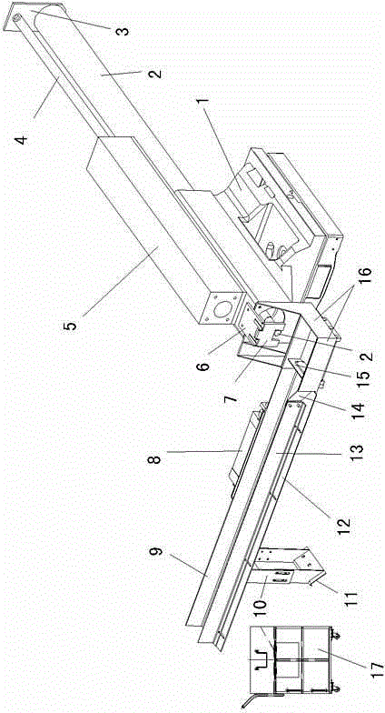
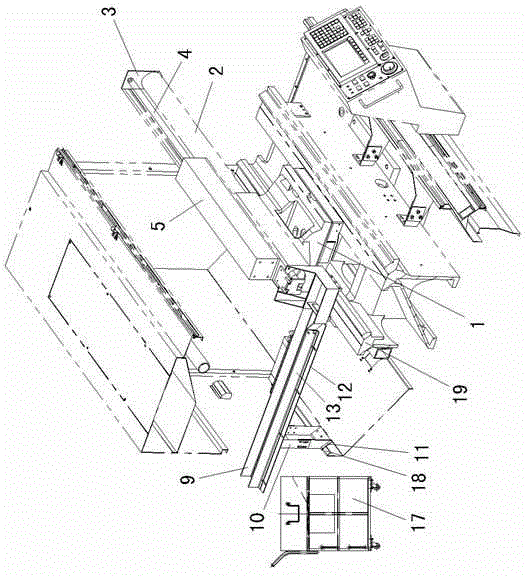
[0010] like figure 1 As shown: 1 is the tailstock body, the upper part of the tailstock body 1 is axially penetrated with a slide bar 2, and the slide bar 2 can slide axially relative to the tailstock body 1. One end of the slide bar 2 is connected to the driving device. The driving device is fixedly connected with the oil cylinder 5 connected with the hydraulic mechanism on the tailstock body 1, and the outer end of the piston rod 4 matched with the oil cylinder 5 is connected with an end of the slide bar 2 through the connecting plate 3. When oil cylinder 5 moves, connecting plate 3 and slide bar 2 can be driven by piston rod 4 to move.

[0011] The front end of the tailstock body 1 is screwed with a flat plate 6 arranged horizontally, and the end of the flat plate 6 is fixedly connected with a baffle plate 7 arranged vertically. The other end of slide bar 2 is positioned at the opening below baffle plate 7, and the termination of slide bar 2 can reciprocate at the opening...


PUM


Abstract

The invention discloses an automatic material preparing device used for preparing materials of plate parts of machining lathe. The automatic material preparing device comprises a tailstock body matching with a guide rail; a sliding rod axially penetrates an upper shaft of the tailstock body, a driving device is connected with one end of the sliding rod, a vertically arranged partition plate is connected with the front end of the tailstock body via a slab, a material collecting box arranged below the partition plate is fixed at the front end of the tailstock body, a spout is communicating with one side of the material collecting box, a push plate is arranged in the spout and the push plate is connected with a pushing mechanism. The automatic material preparing device is simple in structure, convenient to prepare materials, low in cost, easy to operate and control and is time saving and energy saving.

Description

technical field [0001] The invention relates to an automatic unloading device, which is used for automatic unloading of disc parts on a flat bed CNC lathe. Background technique [0002] Most of the existing flat-bed CNC lathes are manually loaded and unloaded when processing disk parts, which is time-consuming and labor-intensive, and has potential safety hazards. In order to overcome the above shortcomings, it is necessary to replace manpower with machines or mechanisms. Therefore, auxiliary machine tools such as manipulators and robots are used on some machine tools. This method is costly, troublesome to operate, and poor in popularity. Contents of the invention [0003] The object of the present invention is to provide an automatic unloading device with simple structure, convenient unloading, low cost, easy operation, easy control, time-saving and labor-saving, so as to overcome the deficiencies of the prior art. [0004] The automatic unloading device of the present i...

Claims


Application Information

Patent Timeline
IPC IPC(8): B23B15/00
CPCB23Q7/08
Inventor 葛江薛志红潘作礼董建军张裕春岳云萍曲道武
Owner 大连机床(数控)股份有限公司
Why Eureka
Try Eureka