Spiral cut milling cutter with convex shoulder

A technology of spiral grooves and shoulders, which is applied in the direction of milling cutters, milling machine equipment, manufacturing tools, etc., can solve the problem of inconsistency in the width of the tool edge, and achieve the effect of consistent appearance quality, increased strength, and good cutting performance

Inactive Publication Date: 2014-02-26
常熟量具刃具厂
View PDF6 Cites 0 Cited by
  • Summary
  • Abstract
  • Description
  • Claims
  • Application Information

AI Technical Summary

Problems solved by technology

[0003] The purpose of the present invention is to provide a spiral flute milling cutter with a shoulder, which solves the problem of inconsistent width of the cutting edge

Method used


Image

  • Spiral cut milling cutter with convex shoulder
  • Spiral cut milling cutter with convex shoulder
  • Spiral cut milling cutter with convex shoulder

Examples


Embodiment Construction

[0013] The present invention will be further described below in conjunction with the examples, but not as a limitation of the present invention.

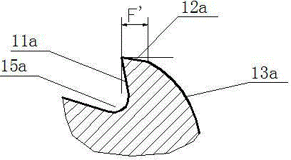
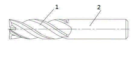
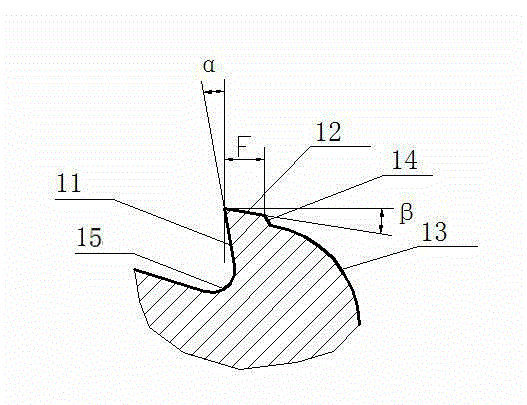
[0014] See figure 2 and image 3 , a spiral groove milling cutter with a shoulder, including a cutting part 1 for cutting work and a tool holder 2 for installation, the tooth shape of the cutting part 1 consists of a front edge face 11, a rear edge face 12, a tooth back 13 and a groove 15, a stepped shoulder 14 is provided at the joint between the rear edge surface 12 and the tooth back 13, and the height of the stepped shoulder 14 is h, so that there is a height difference between the rear edge surface 12 and the tooth back 13. The spiral groove milling cutter of processing band convex shoulder 14 is processed with special-purpose forming milling cutter, and groove and convex shoulder 14 are processed by one-shot molding during processing groove. Since there is a height difference h between the trailing edge surface 12 and the t...


PUM


Abstract

The invention discloses a spiral cut milling cutter with a convex shoulder. The spiral cut milling cutter comprises a cutting part and a cutter handle, wherein a tooth profile of the cutting part is composed of a front blade surface, a rear blade surface, a tooth back and a groove; the convex shoulder is arranged on a connection between the rear blade surface and the tooth back. The milling cutter with the structure has a consistent land width, high tooth profile strength and stable cutting.

Description

technical field [0001] The invention relates to a spiral groove milling cutter, in particular to a spiral groove milling cutter with a convex shoulder. Background technique [0002] Generally, milling cutters are processed by turning and milling first, then blackened by heat treatment or sandblasting, and then ground. During the grinding process, only the front edge face and the rear edge face of the cutting edge are ground, and the milled groove shape is generally not processed. The normal tooth shape of ordinary spiral groove milling cutter is as follows figure 1 As shown, it is composed of front edge surface 11a, rear edge surface 12a, tooth back 13a and groove 15a, etc. Due to machining errors and other reasons at the end of the grinding process, the distance between the cutting edge and the trailing edge surface of the tool and the intersection line of the tooth back, that is, the width F' of the tool margin is inconsistent, and the size of the relief angle during pro...

Claims


Application Information

Patent Timeline
IPC IPC(8): B23C5/10
Inventor 李宪国
Owner 常熟量具刃具厂
Why Eureka
Try Eureka