
Drafting device in spinning frame

A drafting device and spinning frame technology, applied in spinning machines, drafting equipment, textiles and papermaking, etc., can solve the problems of uneven fiber movement, affecting the strength of spinning yarn, and increasing yarn hairiness, so as to improve the strength and Surface smoothness, reduction of single fiber breakage, and improvement of evenness

Inactive Publication Date: 2014-02-26
ZHANGJIAGANG GUANGZHONG TEXTILE MACHINERY TECH CO LTD
View PDF0 Cites 7 Cited by
  • Summary
  • Abstract
  • Description
  • Claims
  • Application Information

AI Technical Summary

Problems solved by technology

[0005] But there are still many disadvantages in the existing drafting device in this spinning frame: due to adopting the above-mentioned double apron drafting form in the main drafting area of ​​this drafting device, the roving strands are in the main drafting area. It is not easy to achieve further untwisting. The double apron structure has a strong control over the roving sliver, and it is easy to cause the fiber breakage in the roving sliver during drafting, thereby affecting the strength of the spun yarn; The drafting control with double aprons is set in the stretching area, and the roving strands are tightened first and then loosened during the drafting process, which may easily cause uneven fiber movement. At the same time, during the drafting process of short fibers, due to the There is a difference in the line speed of the ring, so it is also easy to produce short fibers piled up on each other, and the fiber hooks increase, resulting in an increase in the thick and fine knots of the spun yarn, reducing the evenness of the spun yarn; It is easy to become wider under the compression, and it is easy to cause the width of the front twisting triangle to be large, resulting in increased hairiness of the yarn and affecting the quality of the spun yarn

Method used

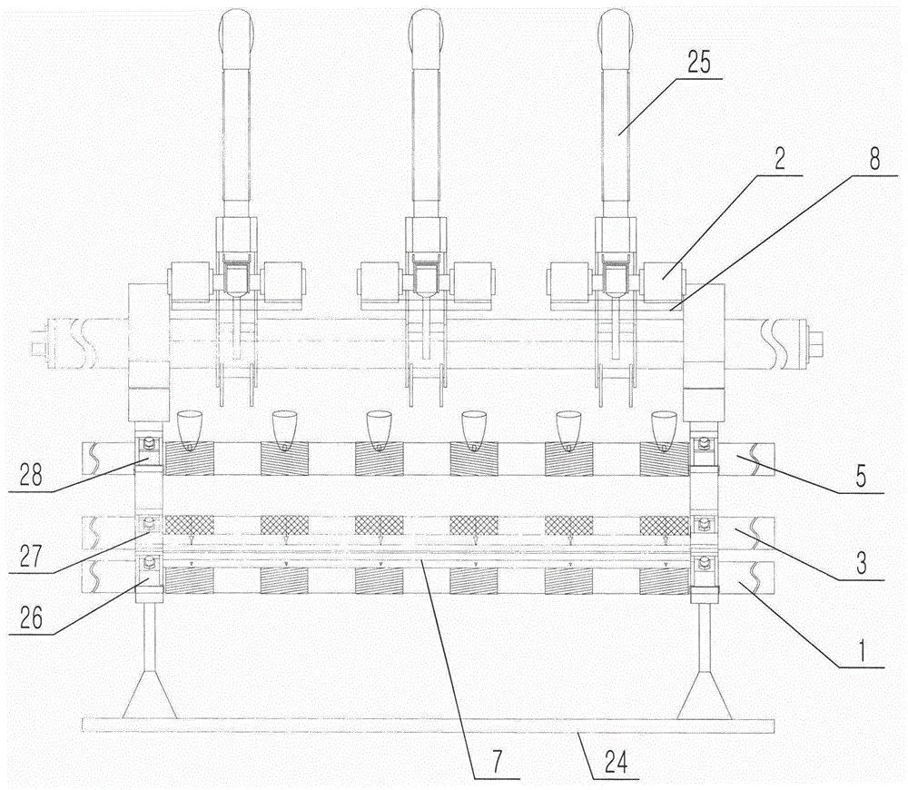
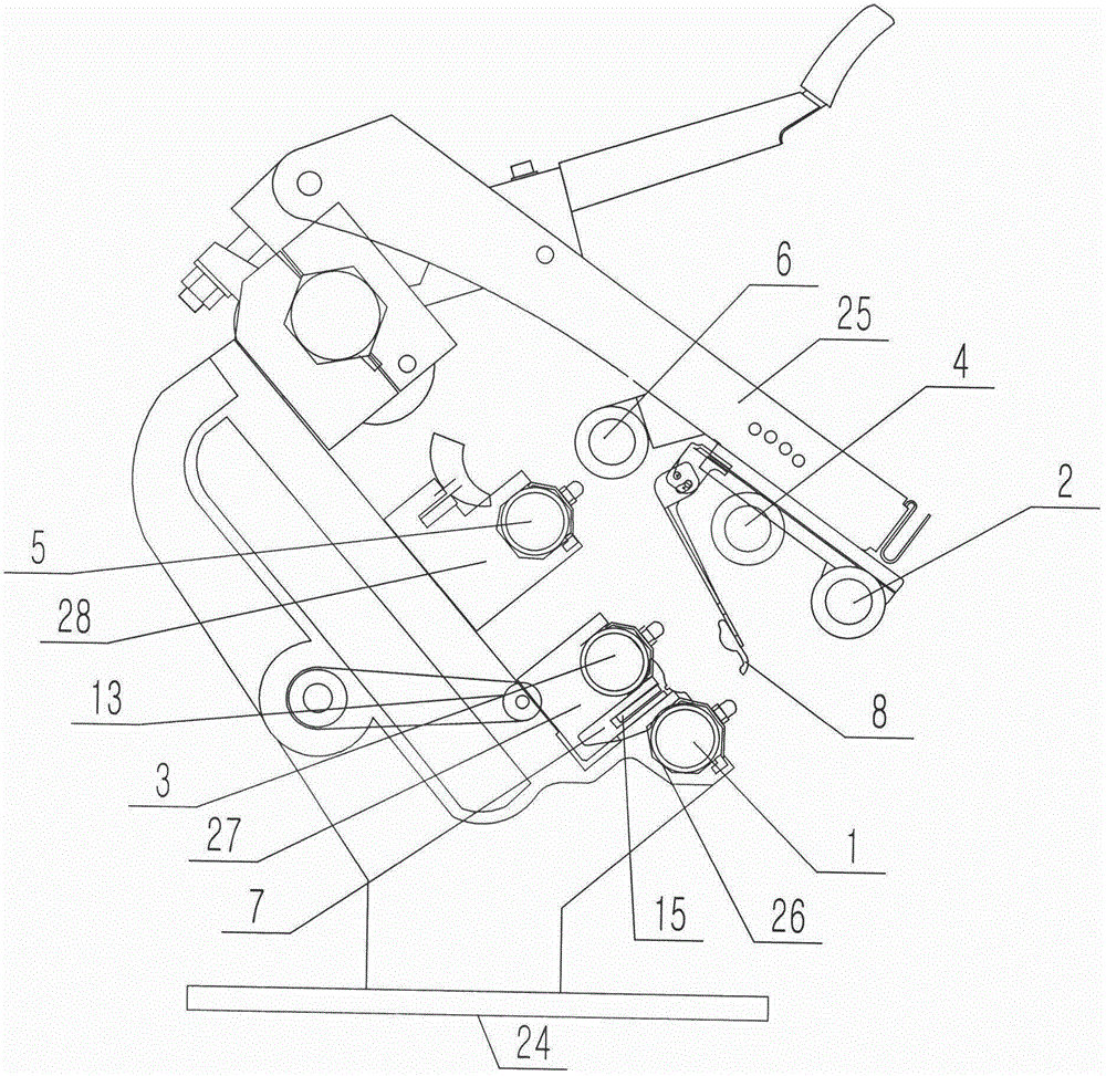
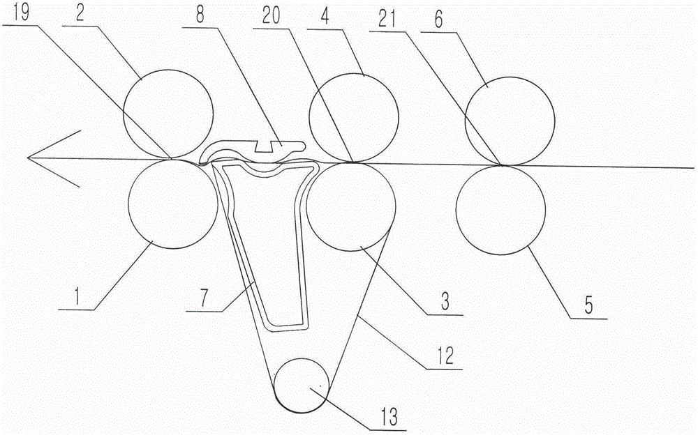

Image

  • Drafting device in spinning frame
  • Drafting device in spinning frame
  • Drafting device in spinning frame

Examples


Embodiment Construction

[0030] The drafting device in the spinning frame according to the present invention will be further described in detail through specific examples below.

[0031] Such as figure 1 , figure 2 , image 3 As shown, the drafting device in the spinning frame includes the frame 24 of the spinning frame, and the three rows of roller seats arranged on the frame 24 are respectively the front roller seat 26, the middle roller seat 27 and the rear roller seat 28, and each row The roller seats in the row are all lined up and evenly distributed; at the same time, the front roller seats 26, middle roller seats 27 and rear roller seats 28 in each row of roller seats correspond to each other and are located in the same plane; the front roller seats 26, middle roller seats Front roller 1, middle roller 3 and rear roller 5 are respectively arranged on seat 27 and rear roller seat 28, and the central axes of front roller 1, middle roller 3 and rear roller 5 are all parallel to each other; fron...


PUM


Abstract

The invention relates to a drafting device in a spinning frame. The drafting device in the spinning frame comprises a front roller, a front leather roller, a middle roller and a middle leather roller. A front jaw is formed between the front leather roller and the front roller, a middle jaw is formed between the middle leather roller and the middle roller, and a negative pressure pipe is arranged between the front roller and the middle roller. A groove is formed in the middle of the upper surface of the negative pressure pipe, a front gathering opening and a rear gathering opening are formed in the upper surface of the negative pressure pipe, and a tension device is arranged below the middle roller and the negative pressure pipe. A flexible sleeve ring made of breathable materials bypasses the upper surface of the middle roller, the upper surface of the negative pressure pipe and the tension device and covers the opening parts of the front gathering opening and the rear gathering opening. An upper pin is arranged above the connecting line of the front jaw and the middle jaw and placed between the front leather roller and the middle leather roller. A cambered surface boss is arranged on the lower surface of the upper pin, the end portion, extending downwards, of the cambered surface boss abuts against the flexible sleeve ring on a groove in the upper surface of the negative pressure pipe. The drafting device in the spinning frame is suitable for the spinning frame, and mainly used for orderly and evenly arraying fibers.

Description

technical field [0001] The invention belongs to the field of textile machinery and relates to a spinning frame, in particular to a drafting device of the spinning frame. Background technique [0002] During the spinning process, the spinning frame makes the roving sliver into spun yarn through the processes of unwinding, feeding, drafting, twisting and winding. Among them, the drafting device of the spinning frame plays a vital role in the speed and quality of spinning. [0003] The drafting device in the traditional spinning frame mainly includes: a frame, a number of roller seats arranged on the frame, and the roller seats are usually arranged in three rows according to the needs, which are respectively the front roller seat, the middle roller seat and the rear roller seat. The roller seats are lined up and evenly distributed; at the same time, the front roller seats, middle roller seats and rear roller seats in each row of roller seats correspond to each other and are lo...

Claims


Application Information

Patent Timeline
Patent Type & Authority Applications(China)
IPC IPC(8): D01H5/18D01H5/72
Inventor 邓万胜
Owner ZHANGJIAGANG GUANGZHONG TEXTILE MACHINERY TECH CO LTD
Learn More