Injecting-plugging method during under-well work

A technology of killing wells and rubber plugs, which is applied in the plugging field of ultra-low pressure oil and gas wells prone to loss. It can solve the problems of complex plugging process of ultra-low pressure wells, increased operation cycle and cost, and low first-time success rate, and achieves process completion. Best, low operating cost and short operating cycle

Active Publication Date: 2014-02-26
BC P INC CHINA NAT PETROLEUM CORP +1
View PDF7 Cites 15 Cited by
  • Summary
  • Abstract
  • Description
  • Claims
  • Application Information

AI Technical Summary

Problems solved by technology

The plugging process of ultra-low pressure wells is complicated and has a low one-time success rate; bridge plugs can seal production layers, but for production layers that need to be permanently sealed, plug injection must

Method used


Image

  • Injecting-plugging method during under-well work
  • Injecting-plugging method during under-well work
  • Injecting-plugging method during under-well work

Examples


Embodiment 1

[0033] As a most basic embodiment of the present invention, its steps are as follows:

[0034] a. After the clear water kills the well, measure the equilibrium liquid level in the well;

[0035] b. After pulling out the original pipe string in the well, put in the casing rubber plug, and send the casing rubber plug to the design depth with the plug injection string;

[0036] c. Pump the cement slurry from the injection pipe string, and then pump clean water to replace the cement slurry. After the pumping is completed, directly raise the injection pipe string to above the measured equilibrium liquid level. After the liquid level in the well reaches the highest dynamic liquid level, The liquid level in the well gradually decreases until the liquid level in the well returns to the equilibrium liquid level;

[0037] d. The cement slurry is allowed to stand and wait until it solidifies, and a cement plug is formed after the cement slurry solidifies.

[0038] In this example, the ...

Embodiment 2

[0040] As the best implementation mode of the present invention, its steps include:

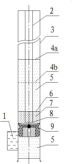
[0041] Clean water 5 kill the well, measure the balance static liquid level 4b after the well kill is stable, pour the same amount of clean water as the total liquid volume of the plugging construction, and measure the balance static liquid level 4b again at intervals of the cement slurry initial setting time, usually the ultra-low pressure is easy to leak wells The equilibrium static liquid level 4b is basically the same; after the balanced static liquid level 4b is measured, the original pipe string in the well is pulled out. 2) Put in the rubber plug 9, and insert the injection plug string 2 and its pipe shoe 8 to the depth

[0042]

[0043] 3) Inject cement slurry 7 from the plugging string 2 to replace the clean water 5. The replacement principle is that the cement slurry interface 6 inside and outside the plugging string 2 is consistent. Cement slurry 7 dosage

[0044]

[0045...


PUM


Abstract

The invention discloses an injecting-plugging method during under-well work. The method is characterized by comprising the following steps: a. killing a well to steady by clear water and then measuring the balance liquid level in the well; b. pulling out an original tube string from the well, throwing a casing rubber plug, and conveying the casing rubber plug to the designed depth by an injecting-plugging tube string; c. pumping cement slurry from the injecting-plugging tube string, then pumping clear water to substitute for cement slurry, and directly pulling the injecting-plugging tube string to the measured balance liquid level after the pumping is finished, wherein the liquid level in the well descends gradually after achieving the highest working liquid level until restoring to balance; and d. standing the cement slurry for waiting for solidifying, and forming a cement plug after the cement slurry is solidified. The method is especially applicable to ultra low pressure oil-gas wells prone to leakage, and capable of directly accomplishing injecting-plugging without stopping leakage or throwing a bridge plug when the level of a well killing fluid in the well is far away from the mouth of the well; the injecting-plugging difficulty of the ultra low pressure wells prone to leakage is effectively overcome.

Description

[0001] technical field [0002] The invention relates to a plug injection method for downhole operation in oil and gas development, in particular to a plug injection method for an ultra-low pressure and easy-to-leakage oil and gas well where circulation or loss of return cannot be established, and the balance liquid level in the well is far away from the wellhead. Background technique [0003] Plug injection is a widely used process in downhole operations of oil and gas development, and plug injection is usually required for operations such as sealing the upper test layer of old layers, opening windows for sidetracking, or scrapping oil and gas wells. Plug injection is to inject cement slurry into a specific section of the wellbore. After standing for a period of time, the cement slurry solidifies to form a cement plug (non-permeable cement stone). According to the petroleum industry standard SY / T 5587.14 Conventional Well Workover Operation Regulations Part 14 Plug injectio...

Claims


Application Information

Patent Timeline
IPC IPC(8): E21B33/13
Inventor 付建华李亮黎自刚胥宏图陈国庆陈良英
Owner BC P INC CHINA NAT PETROLEUM CORP
Why Eureka
Try Eureka