
Silencer

A muffler and cylinder technology, applied in the direction of mufflers, machines/engines, engine components, etc., can solve problems such as unfavorable manufacturing, complex structures of resistant mufflers or impedance composite mufflers, and achieve low cost, simple structure, and good performance. The effect of the noise reduction effect

Inactive Publication Date: 2014-02-26
天津豪记科技有限公司
View PDF0 Cites 28 Cited by
  • Summary
  • Abstract
  • Description
  • Claims
  • Application Information

AI Technical Summary

Problems solved by technology

[0002] In order to eliminate the huge sound produced when the engine discharges the high-temperature and high-pressure gas after combustion, the car needs to install a muffler at the exhaust pipe; The passive muffler absorbs sound energy by filling the exhaust pipe with sound-absorbing material to achieve the purpose of muffled noise; the resistant muffler sharply increases or reduces the cross-sectional area of ​​the pipe at a certain length inside the muffler, so that the sound wave is generated when it propagates. Reflection and Fengri elimination interference can achieve the purpose of noise reduction; the resistance muffler has a better noise reduction effect at low and intermediate frequencies; to improve the high frequency noise reduction effect, the cross-sectional area of ​​the pipeline can be used to have resistance to multiple sharp increases or reductions Muffler or impedance composite muffler, the structure of the current resistant muffler or impedance composite muffler is too complicated, which is not conducive to manufacturing

Method used


Image

  • Silencer

Examples


Embodiment Construction

[0013] Below, the substantive features and advantages of the present invention will be further described in conjunction with examples, but the present invention is not limited to the listed examples.

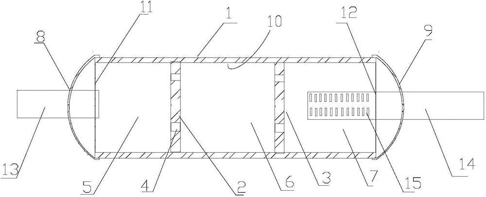
[0014] see figure 1 , a muffler, including a cylinder 1, the cylinder 1 has an air inlet end 11 and an air outlet 12; the cylinder 1 is provided with two partitions 2, 3, the outer walls of the partitions 2, 3 The rim is in sealing connection with the inner wall of the cylinder 1, and the partitions 2, 3 are provided with a plurality of airflow holes 4 along the circumference and near the outer edge, and the partitions 2, 3 connect the cylinder 1 The inner space is divided into three first spaces 5 with different volumes, a second space 6 and a third space 7. The air inlet 11 and the air outlet 12 are connected with an air inlet 13 and an air outlet 14 respectively. 14 is provided with an exhaust hole 15 on the surface of the part protruding into the interior of the cylinder bo...


PUM


Abstract

The invention relates to a silencer which comprises a barrel body. The barrel body is provided with an air inlet end and an air outlet end. Two partition plates are arranged in the barrel body. The outer edges of the partition plates are connected with the inner wall of the barrel body in a sealing mode. A plurality of air current holes are formed in the circumferential direction of each partition plate. The partition plates separate the inner space of the barrel body into a first space, a second space and a third space which are different in volume. The air inlet end and the air outlet end are respectively connected with an air inlet pipe and an air outlet pipe. Exhaust holes are formed in the surface of the part, extending into the barrel body, of the air outlet pipe. Due to the fact that the inner space of the barrel body of the silencer is separated into three spaces different in volume by the partition plates with the air current holes, air currents can be made to be exhausted through an exhaust pipe after being dramatically increased or shrunk and going through several times of abrupt changes, sound waves are made to be reflected for several times to generate offset interference, and sound energy is remarkably reduced and exhausted, so that the purpose of noise elimination is achieved. The silencer achieves good noise elimination effect and is simple in structure and low in cost.

Description

technical field [0001] The invention belongs to the technical field of mufflers, and in particular relates to a muffler. Background technique [0002] In order to eliminate the huge sound produced when the engine exhausts the high-temperature and high-pressure gas after combustion, the car needs to install a muffler at the exhaust pipe; The passive muffler absorbs the sound energy by filling the exhaust pipe with sound-absorbing material to achieve the purpose of muffler; the resistant muffler sharply increases or reduces the cross-sectional area of ​​the pipe in a certain length inside the muffler, so that the sound wave will be generated when it propagates. Reflection and Fengri elimination interference can achieve the purpose of noise reduction; the resistance muffler has a better noise reduction effect at low and intermediate frequencies; to improve the high frequency noise reduction effect, the cross-sectional area of ​​the pipe can be used to have resistance to multipl...

Claims


Application Information

Patent Timeline
IPC IPC(8): F01N1/10F01N1/06
Inventor 王铁兵
Owner 天津豪记科技有限公司
Learn More