High-precision non-uniformity correction method for dynamic adjustment of integration time

A non-uniformity correction and integration time technology, applied in the field of infrared imaging, can solve problems such as unsuitable correction parameters, image saturation or low response value

Active Publication Date: 2014-02-26
THE 3RD ACAD 8358TH RES INST OF CASC
View PDF4 Cites 41 Cited by
  • Summary
  • Abstract
  • Description
  • Claims
  • Application Information

AI Technical Summary

Problems solved by technology

[0006] The technical problem to be solved by the present invention is: in the existing non-uniformity correction method, when the temperature range of the scene is large, the integration time of the infrared detector is fixed, which is easy to cause image saturation or low response value, and the integral needs to be changed during the working process of the detector. Time length, when the correction parameters generated by fixed integration time change, the correction parameters do not adapt

Method used


Image

  • High-precision non-uniformity correction method for dynamic adjustment of integration time
  • High-precision non-uniformity correction method for dynamic adjustment of integration time
  • High-precision non-uniformity correction method for dynamic adjustment of integration time

Examples


Embodiment Construction

[0057] A high-precision non-uniformity correction method with dynamic adjustment of integration time according to the present invention will be described in detail below with reference to the drawings and embodiments.

[0058]A high-precision non-uniformity correction method for dynamic adjustment of integration time of the present invention comprises the following steps:

[0059] step 1

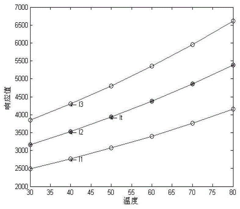
[0060] Collect the detector response value data of each integration time length at different temperatures, and generate figure 2 The temperature-response curves of the detector at different integration time lengths are shown.

[0061] In this embodiment, the collected detector response value data of each integration time length at different temperatures is shown in the following table:

[0062]

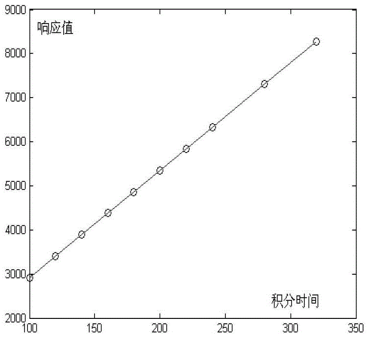
[0063] It can be seen from the above table that the detector response value and the integration time length at a fixed temperature satisfy image 3 The linear relationship shown, the linear r...


PUM


Abstract

The invention belongs to the technical field of infrared imaging, and specifically relates to a high-precision non-uniformity correction method for dynamic adjustment of integration time. The method of the invention comprises the following steps: determining linear relation between a detector response value and the integration time span under a fixed temperature; performing non-uniformity correction; calculating a non-uniformity correction parameter; performing self-adaptive adjustment of the integration time span according to an radiation temperature, determining the section that the integration time span is in, generating the non-uniformity correction parameter in real time in the current integration time, and completing the non-uniformity correction process. The method of the invention realizes continuous adjustability of the integration time in the working process of an infrared detector, solves the problem of inadaptation between the integration time span and the non-uniformity correction parameter of the infrared detector when the change range of the temperature of the scene is large, reduces influence of switching of the integration time on detector performance and recognition tracking, and can give full play to the detection performance of the detector in the working process.

Description

technical field [0001] The invention belongs to the technical field of infrared imaging technology, and in particular relates to a high-precision non-uniformity correction method for dynamic adjustment of integration time. Background technique [0002] The infrared focal plane array imaging system represents the development direction of a new generation of infrared imaging systems. Compared with other thermal imaging systems, it has many advantages such as simple structure, high reliability, high detection sensitivity and high working frame frequency, and has a wide application prospect. However, there is generally inconsistency among the response characteristics of each detection unit of IRFPA, that is, the non-uniformity of response. This inherent problem will cause different degrees of fixed pattern noise interference on the imaged image, obliterating the real imaging information, which is an important factor that seriously restricts the performance of IRFPA imaging syste...

Claims


Application Information

Patent Timeline
Patent Type & Authority Applications(China)
IPC IPC(8): G01J5/00
Inventor 毛贵超张志恒
Owner THE 3RD ACAD 8358TH RES INST OF CASC
Why Eureka
Try Eureka