
Method of Measuring Temperature Using Bragg Grating Array

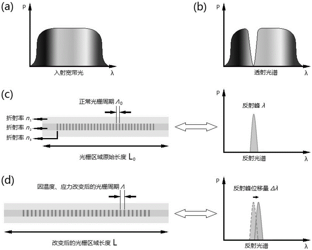
A Bragg grating and temperature measurement technology, which is applied in the application of thermometers, thermometers, measuring devices, etc., can solve the problems of low sensitivity to geometric complexity and the inability to realize temperature distribution, and achieve flexible design and manufacturing, small errors, and space The effect of taking up less

Active Publication Date: 2016-02-17
SHANGHAI JIAOTONG UNIV
View PDF10 Cites 0 Cited by
  • Summary
  • Abstract
  • Description
  • Claims
  • Application Information

AI Technical Summary

Problems solved by technology

2. Low sensitivity to the geometric complexity of manufactured objects
However, this technology cannot realize the simultaneous use of such temperature sensors in a large area to detect the overall temperature distribution of the object.

Method used


Image

  • Method of Measuring Temperature Using Bragg Grating Array
  • Method of Measuring Temperature Using Bragg Grating Array
  • Method of Measuring Temperature Using Bragg Grating Array

Examples


Embodiment 1

[0043] This embodiment includes the following steps:

[0044] Step 1. Determine the structure of the temperature measuring device 4 according to the geometric structure of the object to be measured and the temperature measuring point. A number of Bragg gratings are evenly arranged in the temperature measuring device 4. The temperature measuring device 4 fits the temperature measuring point and introduces A beam of broadband input light 3;

[0045] Step 2. Before the temperature changes, the broadband input light 3 is incident on each Bragg grating 2, and after passing through each Bragg grating 2, the light of the reflection wavelength corresponding to each Bragg grating 2 is reflected back, and the reflected light forms a reference output spectrum; After the temperature changes, the broadband input light 3 is incident on each Bragg grating 2, and after being reflected by each Bragg grating 2, the reflected light forms a changed output spectrum;

[0046] Step 3, comparing the...

Embodiment 2

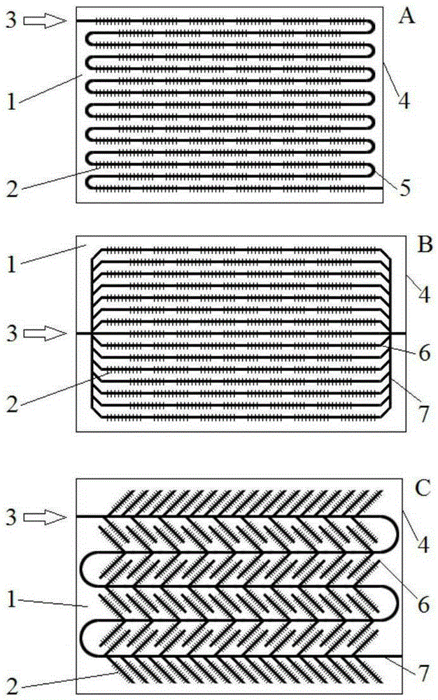
[0062] Such as figure 2 As shown, this embodiment is a temperature measuring device 4 applied to Embodiment 1, including: a chip substrate 1, a number of Bragg gratings 2 arranged in the chip substrate 1 and covering the temperature measurement points of the object to be measured, and broadband input light 3 ,in:

[0063] The arrangement of Bragg gratings 2 is series A, parallel B or series-parallel hybrid C, where:

[0064] The series type A means that all the Bragg gratings 2 in the substrate of the temperature measuring chip are sequentially connected by a waveguide 5 . The incident route of the broadband input light 3 is: sequentially incident on each Bragg grating 2 along the waveguide 5;

[0065] Parallel type B means that each Bragg grating 2 in the substrate of the temperature measuring chip is connected to the trunk waveguide 7 by a branch waveguide 6 . The incident route of the broadband input light 3 is: traveling along the trunk waveguide 7 and splitting the be...


PUM


Abstract

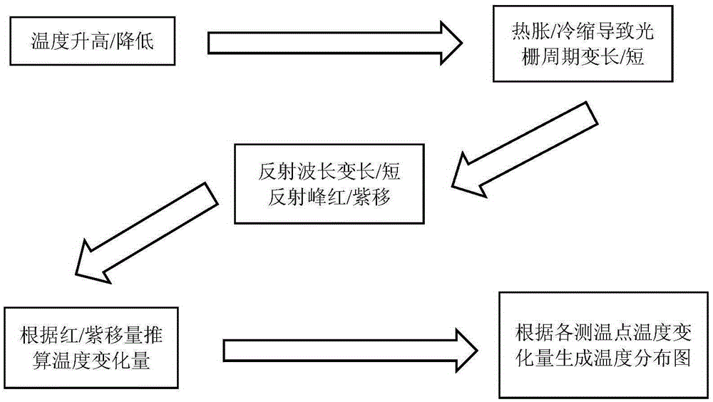
A temperature measurement method using a Bragg grating array in the field of temperature measurement technology. The structure of the temperature measurement chip is determined according to the geometric structure of the object to be measured and the temperature measurement point. Several Bragg gratings are evenly arranged on the temperature measurement device. At the temperature measurement point, a beam of broadband input light is introduced into each Bragg grating; before the temperature changes, the broadband input light is incident on each Bragg grating, and after passing through each Bragg grating, the light of the reflection wavelength corresponding to each Bragg grating is reflected back and is The reflected light forms a reference output spectrum; after the temperature changes, the broadband input light is incident on each Bragg grating, and after being reflected by each Bragg grating, the reflected light forms a changed output spectrum. The changed output spectrum is compared with the reference output spectrum to obtain the wavelength change corresponding to each Bragg grating one by one; the temperature change of each corresponding Bragg grating is obtained according to the wavelength change, so as to obtain the temperature distribution of the temperature measuring device. The invention can measure temperature simply, practically and efficiently.

Description

technical field [0001] The invention relates to a method in the technical field of temperature measurement, in particular to a method for measuring temperature using a Bragg grating array. Background technique [0002] At present, the commonly used temperature detection methods mainly include thermocouple method, electrical parameter method and infrared thermal imaging detection method. The thermocouple method uses a probe to sample the temperature of the target point, which is actually equivalent to using several tiny thermometers to measure the temperature. The response speed is slow, and the range of temperature monitoring is small, which cannot reach the real-time detection of chip temperature. requirements; the electrical parameter method is an indirect rough estimation method, which cannot meet the accuracy requirements of the test chip temperature; the infrared temperature measurement method uses infrared detection equipment to describe the overall temperature distrib...

Claims


Application Information

Patent Timeline
Patent Type & Authority Patents(China)
IPC IPC(8): G01K11/30G01K13/00G01K11/3206
Inventor 金贤敏林晓锋高俊
Owner SHANGHAI JIAOTONG UNIV
Learn More