Power device dynamic characteristic testing circuit with thermoelectric decoupling function and testing method thereof

A power device and test circuit technology, which is applied in the field of power device dynamic characteristic test circuit, can solve the problems of inaccurate switch characteristic test data and affecting the accuracy of test results, etc., and achieve the effect of ensuring the initial ambient temperature

Active Publication Date: 2014-02-26
ZHEJIANG UNIV
View PDF4 Cites 9 Cited by
  • Summary
  • Abstract
  • Description
  • Claims
  • Application Information

AI Technical Summary

Problems solved by technology

Therefore, the switching characteristic test data obtained at this temperature is not accurate, and directly affects the accuracy of the test results

Method used


Image

  • Power device dynamic characteristic testing circuit with thermoelectric decoupling function and testing method thereof
  • Power device dynamic characteristic testing circuit with thermoelectric decoupling function and testing method thereof
  • Power device dynamic characteristic testing circuit with thermoelectric decoupling function and testing method thereof

Examples


specific Embodiment approach 1

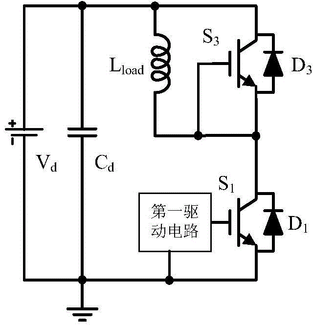
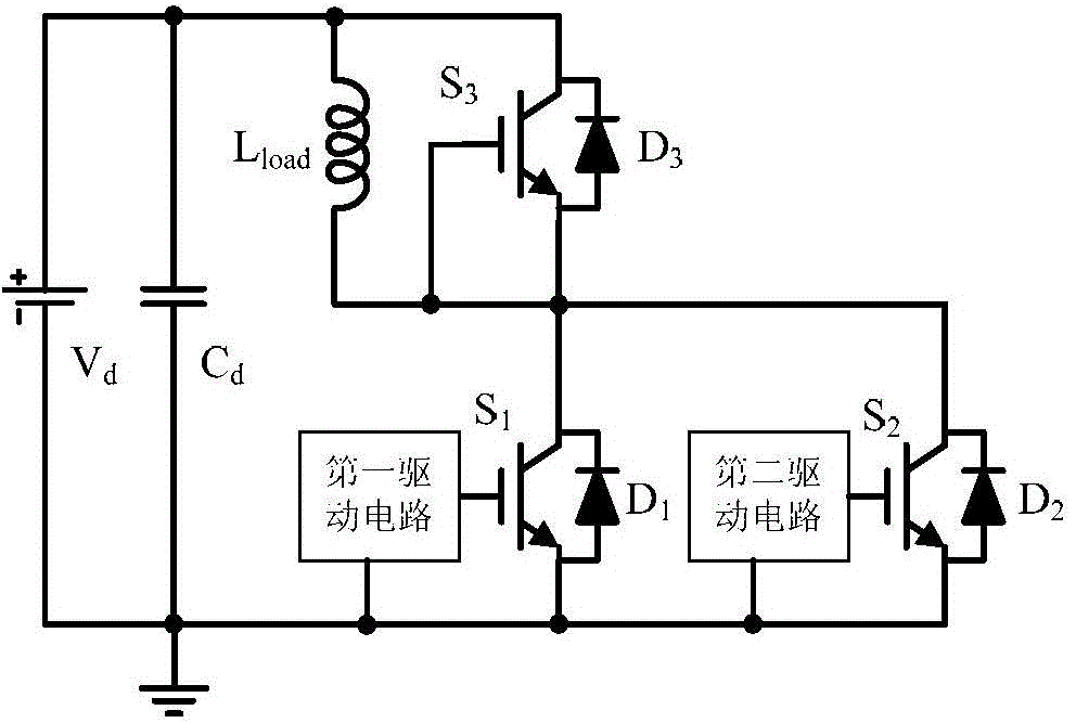
[0030] Such as image 3 As shown, the power switch tube dynamic characteristic test circuit with thermoelectric decoupling function of the present invention includes: a first power switch tube S 1 , the second power switch tube S 2 , the first drive circuit, the second drive circuit, the third power switch tube S 3 , DC power supply V d , DC energy storage capacitor C d , Freewheeling reactor L load ,in:

[0031] Power switch tube S 1 Comes with anti-parallel diode D 1 , power switch tube S 1 Comes with anti-parallel diode D2 , power switch tube S 3 Comes with anti-parallel diode D 3 . Power switch tube S 3 The control input terminal and the off tube S 3 The output terminal of the power switch S is short-circuited. 3 is off, its antiparallel diode D 3 as a freewheeling diode.

[0032] Power switch tube S 1 The input end of the power switch tube S 2 The input end of the power switch tube S 3 The output terminal, and the freewheeling reactor L load One end of ...

specific Embodiment approach 2

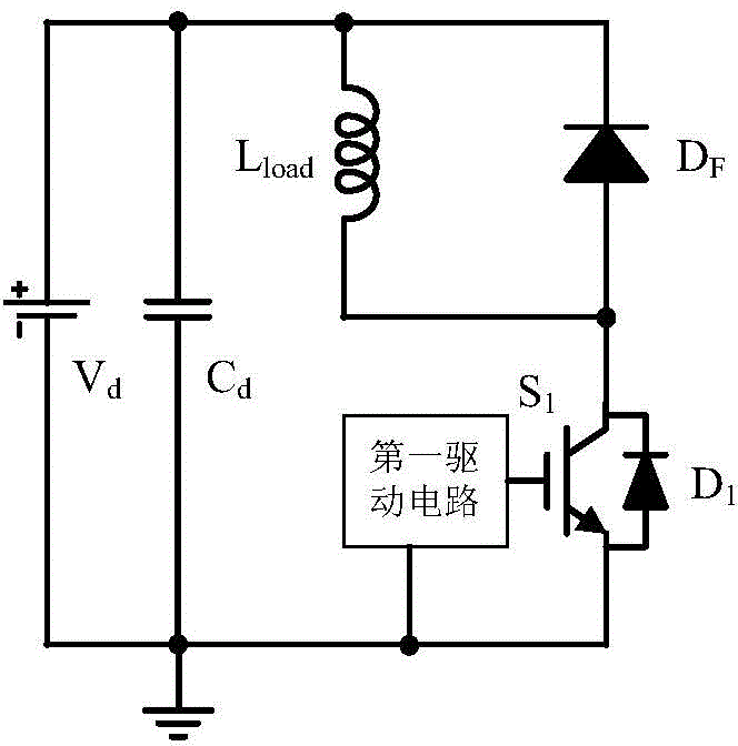
[0033] As another implementation, such as Figure 4 As shown, the freewheeling diode D F for independent power diodes.

[0034] Figure 5 It is a test timing diagram of a conventional power switch tube dynamic characteristic test circuit, and the reference numeral 1 in the figure indicates an unknown temperature point.

[0035] For the power device dynamic characteristic test circuit with thermoelectric decoupling function proposed by the present invention, combined with image 3 In the test circuit, a corresponding thermoelectric decoupling test method is proposed, and the timing diagram of the switch tube test is shown in Figure 6 Shown:

[0036] Step 1, the DC power supply applies a rated DC voltage to the DC energy storage capacitor. Power switch tube S 1 for the device under test. at t 0 Turn on the power switch tube S at all times 2 , while keeping the switching tube S 1 is off state. DC power V d Through the second power switch S 2 For freewheeling reactor...


PUM


Abstract

The invention provides a power device dynamic characteristic testing circuit with the thermoelectric decoupling function. The power device dynamic characteristic testing circuit comprises a first power switching tube S1, a second power switching tube S2, a first driving circuit, a second driving circuit, a third power switching tube S3, a direct-current power source Vd, a direct-current energy storage capacitor Cd and a follow-current electric reactor Lload. The invention further provides a testing method of the testing circuit. The power switching tubes to be tested do not participate in establishment of a load current, so that losses generated in the establishment process of the load current do not affect the temperature of the power switching tubes to be tested, and it is ensured that the environment temperature is stable during a dynamic test for the power switching tubes to be tested.

Description

technical field [0001] The invention belongs to the application field of power electronic devices, and in particular relates to a dynamic characteristic test circuit of a power device with thermoelectric decoupling function and a test method thereof. Background technique [0002] High-power fully-controlled switching devices are widely used in medium and high-power converters. They are one of the core basic components of medium and high-power converters, and the performance of the entire converter is closely related to the dynamic switching characteristics of power devices. Power switching devices will generate voltage spikes, current overshoots and corresponding switching losses due to stray parameters in the power loop during switching transients. The switching characteristics of power devices determine the power density, heat dissipation design, maximum switching frequency, electromagnetic compatibility and system insulation design of the converter to a certain extent. I...

Claims


Application Information

Patent Timeline
Patent Type & Authority Applications(China)
IPC IPC(8): G01R31/327G01R1/44
Inventor 罗皓泽李武华郭清盛况
Owner ZHEJIANG UNIV
Why Eureka
Try Eureka