
Spray head used for MOCVD equipment

A sprinkler head and equipment technology, applied in the sprinkler head field, can solve problems such as poor deposition uniformity

Inactive Publication Date: 2013-11-20
光垒光电科技(上海)有限公司
View PDF5 Cites 6 Cited by
  • Summary
  • Abstract
  • Description
  • Claims
  • Application Information

AI Technical Summary

Problems solved by technology

[0005] The purpose of the present invention is to provide a shower head for MOCVD equipment to solve the problem of poor deposition uniformity of existing MOCVD equipment

Method used


Image

  • Spray head used for MOCVD equipment
  • Spray head used for MOCVD equipment
  • Spray head used for MOCVD equipment

Examples


Embodiment 1

[0030] Please refer to figure 2 , which is a schematic structural diagram of the shower head of the MOCVD apparatus according to Embodiment 1 of the present invention. Such as figure 2 As shown, the shower head 10 of the MOCVD equipment is used to provide reaction gas to the substrate (not shown in the figure) located under the shower head 10. The shower head 10 of the MOCVD equipment includes: a main body layer 11, The side of the main body layer 11 close to the substrate is a gas outlet surface 18, and the reaction gas forms an airflow between the gas outlet surface 18 and the substrate; a restrictor ring 13, the restrictor ring 13 It is connected with the air outlet surface 18 and arranged around the air outlet surface 18 for controlling the direction of the air flow; a heat insulating layer 14 is provided between the restrictor ring 13 and the air outlet surface 18 .

[0031] Specifically, the main body layer 11 is generally made of metal material. The main body layer ...

Embodiment 2

[0035] Please refer to image 3 , which is a schematic structural diagram of the shower head of the MOCVD apparatus according to Embodiment 2 of the present invention. Such as image 3 As shown, the shower head 20 of the MOCVD equipment is used to provide reaction gas to the substrate (not shown in the figure) located under the shower head 20. The shower head 20 of the MOCVD equipment includes: a main body layer 21, The side near the substrate in the main body layer 21 is a gas outlet surface 28, and the reaction gas forms an air flow between the gas outlet surface 28 and the substrate; a restrictor ring 23, the restrictor ring 23 It is connected with the air outlet surface 28 and arranged around the air outlet surface 28 for controlling the direction of the air flow; a heat insulation layer 24 is provided between the restrictor ring 23 and the air outlet surface 28 .

[0036] Specifically, the main body layer 21 is generally made of metal material. The main body layer 21 in...


PUM


Abstract

The invention provides a spray head used for MOCVD equipment. The spray head is used for providing a substrate under the spray head with reaction gas. The spray head comprises a main body layer, wherein a side close to the substrate is a gas outlet face, and gas flows of the reaction gas are formed between the gas outlet face and the substrate; and a flow limiting ring, wherein the flow limiting ring is connected to the gas outlet face, and is arranged around the gas outlet face, so as to control the direction of the gas flows. A thermal insulation layer is arranged between the flow limiting ring and the gas outlet face. According to the spray head used for the MOCVD equipment, the thermal insulation layer is arranged between the flow limiting ring and the gas outlet face, and influences of the flow limiting ring on the temperature of the gas outlet face are avoided, so that uniformity of the deposition of the MOCVD equipment is increased.

Description

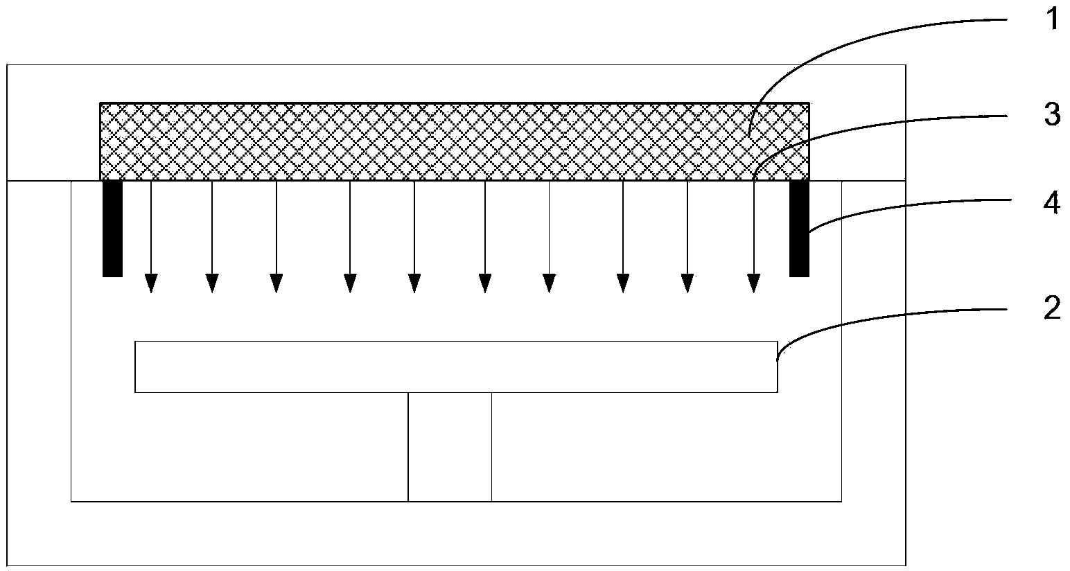
technical field [0001] The invention relates to the technical field of chemical vapor deposition equipment, in particular to a shower head for MOCVD equipment. Background technique [0002] During the Metal Organic Compound Chemical Vapor Deposition (MOCVD) process, Group III source gases and Group V source gases are respectively passed into the reaction chamber through the shower head of the MOCVD equipment, and react to form a film on the heated substrate. Please refer to figure 1 , which is a structural schematic diagram of a reaction chamber of an MOCVD device in the prior art. Such as figure 1 As shown, the shower head 1 for MOCVD equipment is generally arranged above the tray 2, the tray 2 is used to place the substrate, the lower surface of the shower head 1 is provided with an air outlet 3, and the shower head 1 can be The tray 2 is uniformly provided with reaction gas through the air outlet 3 . In order to further improve the uniformity and utilization of the re...

Claims


Application Information

Patent Timeline
Patent Type & Authority Applications(China)
IPC IPC(8): C23C16/455
Inventor 谭华强乔徽林翔苏育家
Owner 光垒光电科技(上海)有限公司
Learn More