Ion beam deposition equipment for infrared metal film and film deposition method

An ion beam deposition, metal film technology, applied in ion implantation plating, metal material coating process, coating and other directions, can solve the problems of difficult control, difficult to prepare large-area thin films, long time to establish vacuum, etc., to improve adhesion. Focus, good deposition uniformity, improve the effect of deposition uniformity

Active Publication Date: 2021-01-01
48TH RES INST OF CHINA ELECTRONICS TECH GROUP CORP
View PDF6 Cites 3 Cited by
  • Summary
  • Abstract
  • Description
  • Claims
  • Application Information

AI Technical Summary

Problems solved by technology

However, the ion beam sputtering equipment used in the preparation of infrared metal films by ion beam deposition is all small-sized substrates and manual scientific research equipment, which has the following problems: (1) does not have the function of independent loading and unloading film chambers, each The door of the thin film deposition chamber (sputtering chamber) needs to be opened after the first sputtering, which has problems such as long time for establishing vacuum and short effective working time; at the same time, the target is often exposed to the atmosphere during the loading and unloading process, which is likely to cause damage to the target. Therefore, it is necessary to burn the target to remove the oxide layer before each use, resulting in waste of the target material and low utilization rate; (2) It is inconvenient to load and unload the material, and the shape of the substrate substrate is single, and it is difficult to be compatible with various special-shaped chips; (3) ) The workpiece table is small in size, so it can only carry small substrates, so it is difficult to prepare

Method used


Image

  • Ion beam deposition equipment for infrared metal film and film deposition method
  • Ion beam deposition equipment for infrared metal film and film deposition method
  • Ion beam deposition equipment for infrared metal film and film deposition method

Examples


Embodiment 1

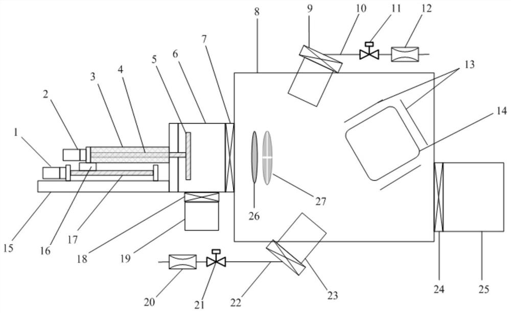
[0044] Such as figure 1 As shown, the ion beam deposition equipment for infrared metal film in this embodiment includes a loading and unloading chamber 6 and a sputtering chamber 8, and a first high vacuum is provided between the loading and unloading chamber 6 and the sputtering chamber 8 Isolation valve 7; Loading and unloading sheet chamber 6 is provided with vacuum sealing door 15, is penetrated with push rod 4 in the vacuum seal door 15, and one end of push rod 4 is provided with workpiece table 5 at the inner side of vacuum seal door 15; There is a propulsion mechanism for pushing the propulsion rod 4; the loading and unloading chamber 6 is connected with a first vacuum device 19. In the present invention, a loading and unloading film chamber 6 is provided on the door side of the sputtering chamber 8. During the film loading process, the first high vacuum isolation valve 7 is closed first to keep the vacuum environment of the sputtering chamber 8 unchanged. , then open ...


PUM


Abstract

The invention discloses ion beam deposition equipment for an infrared metal film and a film deposition method. The equipment comprises a wafer loading and unloading cavity and a sputtering cavity, wherein a first high-vacuum isolation valve is arranged between the wafer loading and unloading cavity and the sputtering cavity, the wafer loading and unloading cavity is provided with a vacuum sealingdoor, a pushing rod penetrates through the vacuum sealing door, a workpiece table is arranged at the end, on the inner side of the vacuum sealing door, of the pushing rod, a pushing mechanism used forpushing the pushing rod is arranged on the outer side of the vacuum sealing door, and the wafer loading and unloading cavity is connected with a first vacuumizing device. The film deposition method adopts the equipment to perform film deposition. According to the invention, the wafer loading and unloading cavity is arranged, so that the cavity opening and vacuumizing times of the sputtering cavity can be reduced, the vacuumizing time can be shortened, the productivity can be improved, the vacuum environment can be always kept in the sputtering cavity, the target burning times can be reduced,and the utilization rate of a target material can be improved. The ion beam deposition equipment has the advantages of high productivity, high target material utilization rate and the like, can be widely used for depositing infrared metal films, and has very high use values and application prospects.

Description

technical field [0001] The invention relates to an ion beam deposition equipment and a thin film deposition method for infrared metal films. Background technique [0002] Ion beam thin film deposition technology is one of the most important technologies in various coating technologies, and is widely used in the fields of sensors, microelectronics, optical thin films and material surface treatment. Infrared focal plane detector is the key device of modern infrared thermal imaging system, which includes two parts: infrared detector array and readout circuit. As the detection range of infrared focal plane detectors becomes wider and higher, and the detection accuracy becomes higher and higher, the requirements for the array of core components of the detector and the readout circuit are higher and higher. At present, the metal thin film of the infrared detection device chip (that is, the infrared metal film) is mainly prepared by magnetron sputtering and evaporation coating, an...

Claims


Application Information

Patent Timeline
IPC IPC(8): C23C14/46C23C14/56C23C14/54C23C14/02
CPCC23C14/46C23C14/566C23C14/3407C23C14/541C23C14/544C23C14/022Y02P70/50
Inventor 罗超胡凡范江华程文进陈特超
Owner 48TH RES INST OF CHINA ELECTRONICS TECH GROUP CORP
Why Eureka
Try Eureka