Unlock instant, AI-driven research and patent intelligence for your innovation.

Camera view field calibrating method and device

A calibration method and camera technology, applied in measuring devices, optical devices, televisions, etc., can solve problems such as methodological errors, failure to truly reflect the range of camera reception, and difficulty in determining the nodes of the camera optical system, so as to improve accuracy and Repeatability, error avoidance, and effect of improving test accuracy

Inactive Publication Date: 2014-02-26
XI'AN INST OF OPTICS & FINE MECHANICS - CHINESE ACAD OF SCI
View PDF2 Cites 7 Cited by
  • Summary
  • Abstract
  • Description
  • Claims
  • Application Information

AI Technical Summary

Problems solved by technology

[0008] The above two methods are difficult to determine the nodes of the camera optical system, and there are methodological errors, which cannot truly reflect the range of imaging and reception that the camera can receive.

Method used


Image

  • Camera view field calibrating method and device
  • Camera view field calibrating method and device
  • Camera view field calibrating method and device

Examples


Embodiment Construction

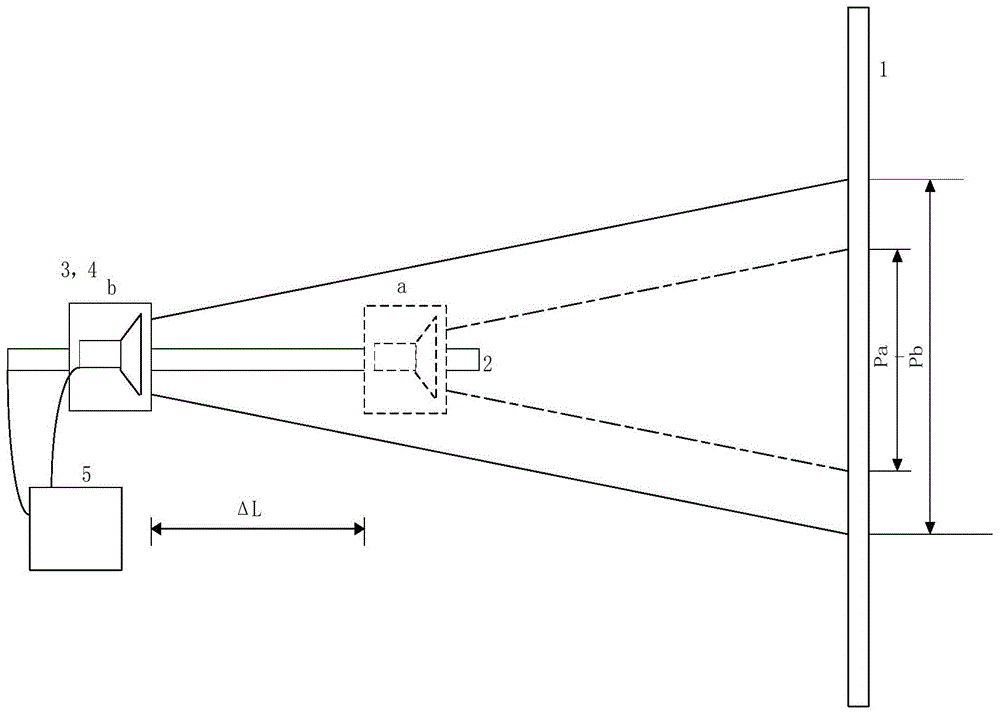
[0026] Principle of the present invention is:

[0027] This method measures the line field of view under the two camera distances and the distance between the two camera distances, utilizes the similarity of the imaging of cameras at different camera distances, and uses the triangular similarity principle to accurately measure the position of the camera node and accurately obtain the camera camera distance. , to achieve the calibration of the camera field of view.

[0028] The invention provides a method for calibrating the field of view of a camera. The method for calibrating the field of view of a camera includes the following steps:

[0029] 1) Attach a flat reflector to the center of the target plate, and use a laser to adjust the electric translation stage so that its running direction is perpendicular to the plane of the target plate. After the adjustment, paste the characteristic circular figure on the center of the target board 1;

[0030] 2) Adjust the position of t...


PUM


Abstract

The invention relates to a camera view field calibrating method and device. The device comprises an imaging object, a camera moving supporting assembly and a control computer. The control computer is connected with the camera moving supporting assembly, and a camera to be calibrated is arranged on the camera moving supporting assembly and conducts imaging on the imaging object. The camera view field calibrating method and device can improve test precision.

Description

technical field [0001] The invention belongs to the field of photoelectric testing, and relates to a method and device for calibrating the field of view of a camera, in particular to a method and device for calibrating the field of view of a close-range imaging camera. Background technique [0002] The camera is generally composed of an optical system and a detection system (usually a CCD or CMOS device). The field of view of a camera represents the imaging range of a camera device and is an important indicator of a camera. [0003] At present, the calibration method of the camera's field of view can be divided into angular field of view and linear field of view due to different definition methods: [0004] (1) The angular field of view refers to the angular range that the camera can image and receive. The test method is to fix the installation surface of the camera and the plane of the turntable, and make the object-space node of the camera optical imaging system coincide...

Claims


Application Information

Patent Timeline
Patent Type & Authority Applications(China)
IPC IPC(8): G06T7/00G06F17/10H04N5/232G01B11/00
Inventor 李坤陈永权赵建科段亚轩龙江波曹昆
Owner XI'AN INST OF OPTICS & FINE MECHANICS - CHINESE ACAD OF SCI