Cell voltage equalizing control method using dynamic reference

A voltage equalization control and voltage technology, applied in battery circuit devices, current collectors, electric vehicles, etc., can solve the problems of short equalization time, increased overall charging equalization time, large equalization error, etc. Simple structure and long balanced effect

Inactive Publication Date: 2014-02-26
JIANGSU JIAYU NEW POWER TECH
View PDF4 Cites 14 Cited by
  • Summary
  • Abstract
  • Description
  • Claims
  • Application Information

AI Technical Summary

Problems solved by technology

When the above-mentioned one-way and two-way converters are combined to charge or discharge the whole battery pack, it is a centralized equalization. The advantage is that the cost and technical complexity of the converter are greatly reduced. The main disadvantages are: the balance between the circuit and each monomer. The wire length and shape are different, the transformation ratio is different, the equalization error is large, and the power wire wiring between the equalization circuit and the battery pack is complicated
[0011] These equalization methods or devices all have some battery cells that are released and lost after being overcharged or transferred to some cells that are undercharged, and there is energy loss during the secondary transfer. The battery cells are charged first and then discharged, which will also affect the battery charging cycle life
In addition, these equalization chargers all use an equalization range as the basis for the high or low voltage of the single battery, but the range of the single cell voltage changes during the battery charging process is relatively large, and this fixed equalization range is used as the basis for equalization The method can only be carried out in the later stage of charging or after charging is completed, which will increase the overall charging equalization time, or lead to a shorter equalization time, which will affect the equalization effect

Method used


Image

  • Cell voltage equalizing control method using dynamic reference
  • Cell voltage equalizing control method using dynamic reference

Examples


Embodiment 1

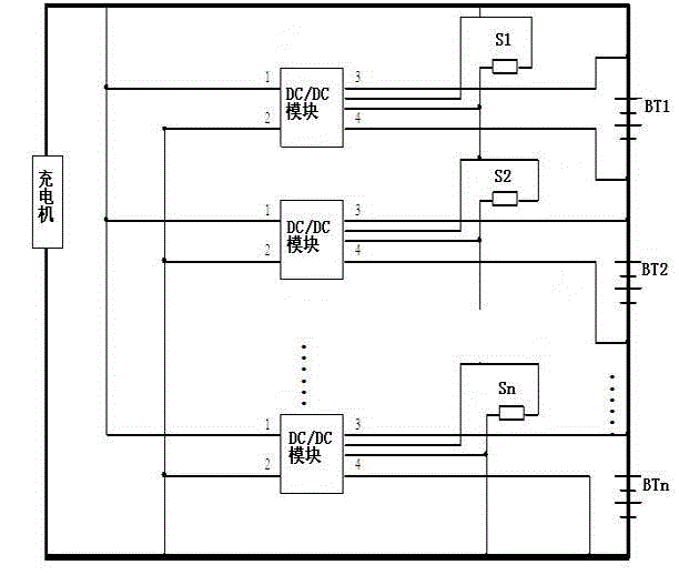
[0032] see figure 2, BT1, BT2..., BTn are battery cells in the series battery pack, and the charger is connected to the series battery pack in parallel to charge the series battery pack. A DC / DC module and a voltage-dividing sampling resistor are connected in parallel between the positive and negative electrodes of each battery cell BT1, BT2..., BTn. The voltage-dividing sampling resistors corresponding to the battery cells BT1, BT2..., BTn are sampling Resistors S1, S2..., Sn. The resistance value of each voltage-dividing sampling resistor is equal to the number of battery cells. The voltage-dividing sampling resistor is used to sample the total output voltage of the battery pack in real time, and the total output voltage is the average cell voltage.

[0033] The DC / DC module can be a power conversion module of various topologies such as forward type, flyback type, and BUCK-BOOST (boost-boost converter). While the charger is charging the battery pack, each voltage-dividin...


PUM


Abstract

The invention discloses a cell voltage equalizing control method using a dynamic reference in a storage battery field. Each cell monomer in a series battery is connected in parallel with an equalization module. A charger is used to charge the series battery. A total output voltage of the battery is sampled in real time. Each monomer voltage of the battery is detected and a reference voltage reference is calculated. When the cell monomer voltage is higher than the reference voltage reference, the corresponding equalization module stops working. When the cell monomer voltage is lower than the reference voltage reference, the equalization module charges the corresponding cell monomer so that voltages of all the cell monomers are equalized. When one cell monomer voltage reaches a monomer protection voltage point, the charger stops charging the battery and each equalization unit continues to carry out boosting charge on the needed monomer till that all the monomer voltages reach the monomer protection voltage point or the monomer voltages are equalized. Output voltages of the equalization units are the same so that a consistency of a final cell voltage is ensured and an equalization effect is good.

Description

Technical field [0001] The invention involves the field of battery storage, and specifically involves the average pressure control method of each single battery in the battery. Background technique [0002] The battery is composed of multiple monomer batteries, and the battery pack consists of multiple batteries in series. It has been widely used in electronic devices in the fields of transportation, power, and communication.Practice shows that the life of the battery pack is far lower than the life of a single battery. The most fundamental reason is that when the charging equipment is charged to the battery pack, the current flows through the batteryDifferences, when charging the same charging current, will cause the battery to discharge the depth of different discharge. The capacity of large capacity will be shallow and shallow, and the capacity of small capacity will always be overly charged.Extension, battery attenuation with small capacity, shortening life, and the differenc...

Claims


Application Information

Patent Timeline
Patent Type & Authority Applications(China)
IPC IPC(8): H02J7/00H02J7/34
Inventor 吴连日
Owner JIANGSU JIAYU NEW POWER TECH
Why Eureka
Try Eureka