
An electric power network device fault diagnosis method and a system

A power network and fault diagnosis technology, applied in the power network operating system integration, transmission system, digital transmission system, etc., can solve wasteful, can't be off-grid faults and send back to the network management, the fault can not intelligently determine the root cause of the fault and fast fault Positioning and other issues to achieve the effect of low loss

Active Publication Date: 2014-02-26
STATE GRID CORP OF CHINA +2
View PDF4 Cites 5 Cited by
  • Summary
  • Abstract
  • Description
  • Claims
  • Application Information

AI Technical Summary

Problems solved by technology

On the one hand, these problems have caused great difficulties to the operation and maintenance of the power communication network, and the cost of operation and maintenance remains high; on the other hand, they have also caused a large number of power network resources to be idle and wasted, affecting further construction and planning
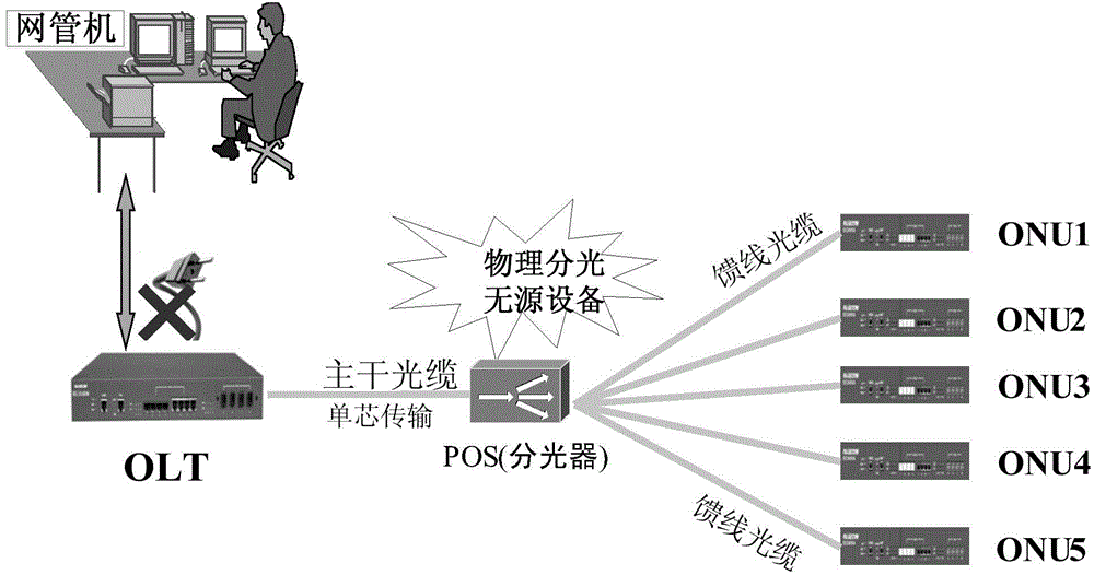
[0006] like image 3 As shown, taking the EPON network as an example, once the OLT is interrupted in the traditional situation, ONU1~ONU5 will not be able to transmit the off-network fault back to the network management because they cannot communicate with the network management, and eventually the network management will only find that the OLT is interrupted and will not Intelligent analysis shows that ONU1 to ONU5 will be interrupted
Furthermore, whether the network failure is caused by OLT interruption or POS interruption cannot be confirmed
[0007] The defect of this technology is that it does not analyze according to the topology of the network, and it cannot intelligently judge the root cause of the fault and quickly locate the fault for complex faults

Method used


Image

  • An electric power network device fault diagnosis method and a system
  • An electric power network device fault diagnosis method and a system
  • An electric power network device fault diagnosis method and a system

Examples


Embodiment

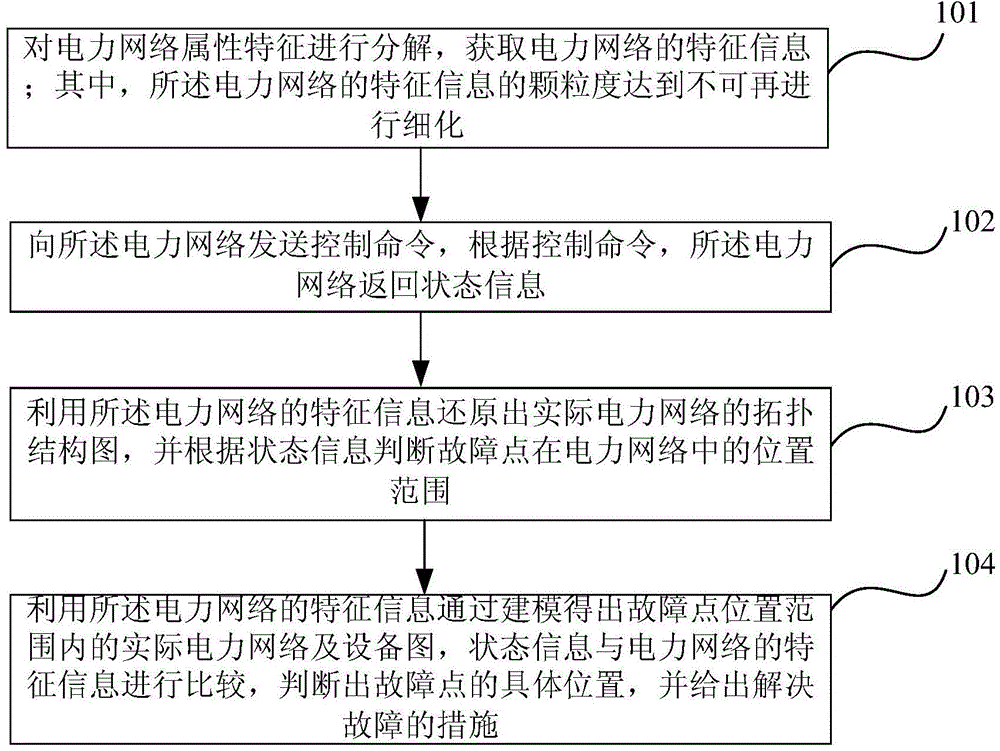
[0063] by image 3 For example, when a fault occurs, the centralized control room sends control commands to the power network to obtain status information of each part of the power network. The linear association model is used to decompose the topology information of the power network. Firstly, it is analyzed that the network management is composed of network management, OLT, POS, ONU1, ONU2, ONU3, ONU4, ONU5 equipment. The topological route from the network management to the OLT is network management-OLT, and the route from the network management to ONU1 is network management-OLT-POS-ONU1 and so on. The conclusion can be drawn after topological analysis. If the OLT is interrupted, not only the device is interrupted, but also POS, ONU1, ONU2, ONU3, ONU4, and ONU5 devices will all be interrupted. Delineate the location of the fault point according to the status information. On this basis, the mapping model is used to decompose the business logic information in the power netw...


PUM


Abstract

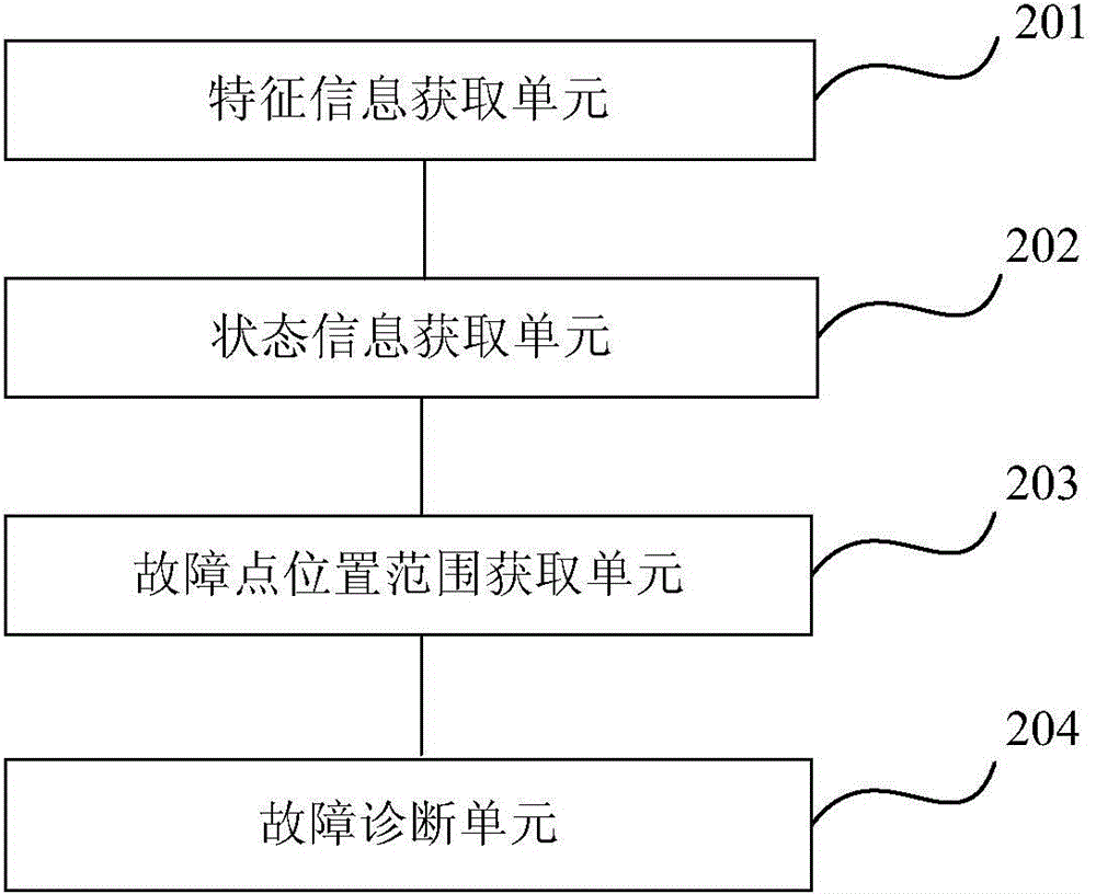
The invention relates to an electric power network device fault diagnosis method and a system. The method comprises the following steps: attribute characteristics of an electric power network is subjected to decomposition in order to obtain characteristic information of the electric power network, and the characteristic information is used as input data of modeling, wherein a granularity of the characteristic information of the electric power network can not be further refined; control commands are sent to the electric power network, and according to the control commands, the electric power network returns state information; a real topological structure graph is obtained by means of utilizing the characteristic information of the electric power network through the modeling, and a position scope of a fault point in the electric power network is determined according to the state information; graphs of a real electric power network and a device of the position scope of the fault point are obtained by means of utilizing the characteristic information of the electric power network through the modeling; and state information is compared with the characteristic information of the electric power network to determine a specific position of the fault point, and measurements for solving the fault are given.

Description

technical field [0001] The invention relates to the field of electric power fault processing, in particular to a fault diagnosis method and system for power network equipment. Background technique [0002] Communication scheduling is the organization, command, guidance and coordination of communication signals in order to ensure the safety, quality and economic operation of various industries. With the development of communication technology, communication conditions have been greatly improved. The original analog channels are gradually replaced by digital channels, which have the advantages of high speed, stability, and reliability; the communication medium transitions from the original carrier wave, wired cable, analog microwave, wireless, etc. to the current optical fiber, digital microwave, etc., communication scheduling More and more computer network communication is used, the network capacity is getting larger and larger, and new equipment emerges in an endless stream...

Claims


Application Information

Patent Timeline
Patent Type & Authority Applications(China)
IPC IPC(8): H02J13/00H04L12/24
CPCY02B70/30Y04S20/20
Inventor 吕海军郭加齐徐鹏宋扬于然李信许鸿飞田宇闫磊常海娇纪雨彤张辉金燊那琼澜李环瑗马跃李旺闫忠平
Owner STATE GRID CORP OF CHINA
Learn More