
Active infrared camera

An active infrared and camera technology, which is applied in the field of infrared network camera devices and active infrared network cameras, can solve the problem that clouds and forest fires in forest areas cannot be effectively distinguished, and visible light cameras do not have the functions of temperature measurement, night vision, and visible light. Problems such as camera viewing distance and field of view limitations, to achieve the effect of easy quality assurance, fine picture quality, and simple structure

Inactive Publication Date: 2014-02-26
CHENGDU JINGLIN ELECTRONICS TECH
View PDF8 Cites 7 Cited by
  • Summary
  • Abstract
  • Description
  • Claims
  • Application Information

AI Technical Summary

Problems solved by technology

[0009] In order to overcome the fact that the visible light camera used in the prior art does not have the functions of temperature measurement and night vision, it can only work in the daytime when the light intensity is relatively good, and cannot effectively distinguish clouds and forest fires in forest areas. The field average is very limited, and a large number of deployments are required in forested areas. Passive infrared cameras used for military use use the infrared light emitted by the object itself as the light source. This kind of camera equipment is expensive and cannot reflect the surrounding environment, so it is not suitable for forested areas. Monitoring and other technical defects, the present invention provides an active infrared camera

Method used


Image

  • Active infrared camera

Examples


Embodiment 1

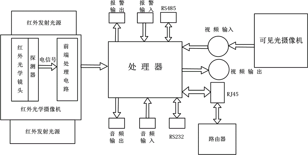
[0047] Such as figure 1 As shown, the present invention includes a visible light camera, an RJ45 interface, a processor integrated with a video codec circuit, an infrared optical camera, and an infrared emitting light source. The infrared emitting light source includes a plurality of infrared lamp beads and is coaxially arranged on the infrared optical camera on the lamp holder, the infrared lamp bead matrix is ​​arranged on the lamp holder; the digital output end of the infrared optical camera is connected to the digital signal input end of the processor, and the video signal output end of the visible light camera is connected to the video signal of the processor The input end, the communication signal end of the processor is connected to the RJ45 interface, and the RJ45 interface is connected to the router through a network cable.

Embodiment 2

[0049] In order to improve the environmental adaptability of the infrared emitting light source of the active infrared camera, this embodiment is further improved on the basis of Embodiment 1. The infrared lamp beads in this embodiment are single-chip infrared lamp beads, array infrared lamp beads, and dot matrix Any one or any combination of infrared lamp beads.

Embodiment 3

[0051] In order to improve the infrared light projection capability of the infrared emitting light source of the active infrared camera, this embodiment is further improved on the basis of any one of the embodiments 1-2. The front end of the infrared lamp bead in this embodiment is provided with a condenser lens.


PUM


Abstract

The invention discloses an active infrared camera. The active infrared camera comprises a visible light camera, an RJ45 interface, a processor with a video encoding and decoding circuit integrated therein, an infrared optical camera and an infrared emission light source, wherein the infrared emission light source comprises multiple infrared lamp beads and a lamp base coaxially arranged on the infrared optical camera; the infrared lamp beads are symmetrically arranged on the lamp base; the digital output end of the infrared optical camera is connected with the digital signal input end of the processor; the video signal output end of the visible light camera is connected with the video signal input end of the processor; the communication signal end of the processor is connected with the RJ45 interface; and the RJ45 interface is connected with a router through a network line. By using the active infrared camera, data acquisition can be provided for forest fire prevention monitoring around the clock in all regions for 7*24 hours in a high-quality and multi-application mode finally.

Description

technical field [0001] The invention relates to the field of security technology, in particular to an infrared network camera, more specifically to an active infrared network camera. Background technique [0002] Forests have the functions of air purification, soil consolidation and water conservation, maintenance of ecological balance, and provision of means of production. In recent years, sandstorms have occurred frequently in our country, and desertification has continued to intensify, which is closely related to the destruction of forests. Every year, a certain number of forest fires occur around the world. Forest fires are characterized by suddenness, uncertainty, and huge damage in a short period of time. Large-scale forest fires are often caused by inconspicuous hidden fires. [0003] Initially, humans built watchtowers and manually guarded forest fires to warn of forest fires. In this way, only large forest fires could be found; later, air cruises were used to moni...

Claims


Application Information

Patent Timeline
Patent Type & Authority Applications(China)
IPC IPC(8): H04N5/225G01J5/08
Inventor 殷刚
Owner CHENGDU JINGLIN ELECTRONICS TECH
Learn More