Transverse steel moving and billet discharging device

A blanking device and a steel-moving technology, which is applied in the field of horizontal steel-moving blanking devices, can solve problems such as unsatisfactory and inflexible

Active Publication Date: 2014-03-05
BERIS ENG & RES CORP
View PDF7 Cites 7 Cited by
  • Summary
  • Abstract
  • Description
  • Claims
  • Application Information

AI Technical Summary

Problems solved by technology

Its equipment is suitable for fixed billet varieties, and is fixed on the foundation of civil engineering, which does not have flexibility and cannot meet the requirements of one continuous casting machine to produce billets with multiple cross-sections.

Method used


Image

  • Transverse steel moving and billet discharging device
  • Transverse steel moving and billet discharging device

Examples


Embodiment Construction

[0019] In order to better understand the purpose of the present invention, the structure and function of the device for laterally moving steel and billet ejection according to the present invention will be described in detail below in combination with the background of the present invention, drawings and actual working conditions.

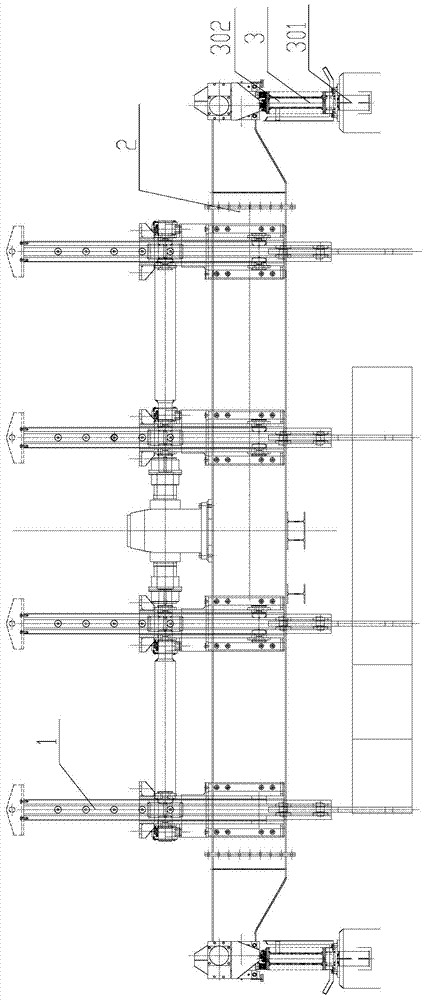
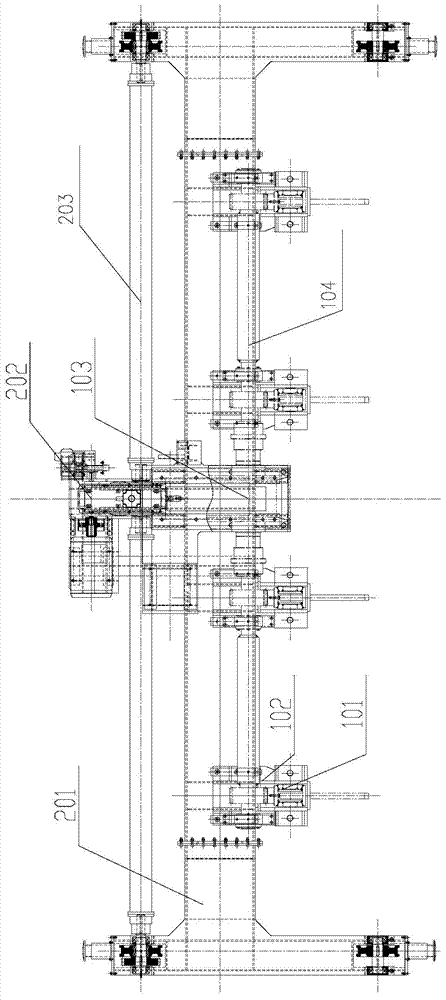
[0020] figure 1 and figure 2 They are respectively the front structural schematic diagram and the top view structural schematic diagram of the laterally moving steel blanking device of the present invention. It can be seen from the figure that the device for laterally moving steel billets of the present invention mainly includes a supporting walking beam device 3 , a laterally moving frame device 2 , and a lifting mechanism 1 .

[0021] The supporting walking beam device 3 can be fixed on the civil foundation through several supporting supports 301, and the supporting supports 301 are equipped with two parallel running beams 302; The track and t...


PUM


Abstract

The invention provides a transverse steel moving and billet discharging device. The transverse steel moving and billet discharging device comprises at least one lifting mechanism (1) and a transverse movement machine frame device (2). Each lifting mechanism comprises a steel catching lifting frame (101) and a power source (103) used for lifting the steel catching lifting frame (101). The steel catching lifting frames (101) are evenly distributed on the transverse movement machine frame device (2). The power sources are fixed to a frame of the transverse movement machine frame device (2). A gear of a power output shaft of each power source is meshed with a rack on the corresponding steel catching lifting frame (101), so that rotation of the power source is converted into longitudinal movement of the steel catching lifting frame. By the adoption of the transverse steel moving and billet discharging device, the collection speed of casting billets is improved, and the operation efficiency of a casting machine is improved. The transverse steel moving and billet discharging device has the advantages that the structure is simple, the billet discharging speed is high, and the billet discharging position is controllable.

Description

technical field [0001] The invention relates to the field of continuous steel casting equipment in the metallurgical industry, in particular to a device for laterally moving steel and discharging billets. Background technique [0002] In the field of continuous casting machine production in the metallurgical industry, the billet cut to length will be transported to the cooling bed area, and then collected, stored, and transported according to process requirements. Whether the efficiency of the collection and transportation equipment can meet the high-speed production requirements of the continuous casting machine will become a direct factor affecting the productivity of the entire continuous casting production line. [0003] At present, the collection equipment used in the cooling bed area of ​​the continuous casting machine is mainly in the form of a stepping cooling bed. The walking cooling bed adopts the form of moving beam / static beam, and makes it move relative to tran...

Claims


Application Information

Patent Timeline
Patent Type & Authority Applications(China)
IPC IPC(8): B22D11/128
Inventor 丁多发
Owner BERIS ENG & RES CORP
Why Eureka
Try Eureka