Anisotropic multipole magnet ring forming mold system

A technology for forming molds and multi-pole magnetic rings, which is used in the manufacture of inductors/transformers/magnets, electrical components, circuits, etc., which can solve the problems of low pressing efficiency, difficulty in providing magnetic field strength for permanent magnet material poles, and difficulty in further improving the performance of multi-pole magnetic rings. Improve and other problems to achieve the effect of small charging power

Inactive Publication Date: 2014-03-05
丁世瑜
View PDF7 Cites 6 Cited by
  • Summary
  • Abstract
  • Description
  • Claims
  • Application Information

AI Technical Summary

Problems solved by technology

However, in this method, during the feeding process of compression molding, due to the attraction of the magnetic material particles by the magnetic field of the permanent magnet material, the material is blocked at the mouth of the mold cavity, so that the material cannot enter the mold cavity, so automatic feeding and compression molding cannot be realized. , this kind of mold can only be made into a manual mold in which the mold cavity block and the mold cavity wall can be separated. The specific operation process is: first manually weigh a certain amount of material, add it to the mold cavity, and then insert it into the mold The cavity block is pressed after adding the upper and lower die heads. After the pressing, the mold cavity and the mold cavity wall are separated, and the blank is taken out to prepare for the next pressing
Therefore, the pressing efficiency of this method is low, and because the magnetic poles of permanent magnet materials are difficult to provide higher magnetic field strength, it is difficult to further improve the performance of the multi-pole magnetic ring

Method used


Image

  • Anisotropic multipole magnet ring forming mold system
  • Anisotropic multipole magnet ring forming mold system
  • Anisotropic multipole magnet ring forming mold system

Examples


Embodiment Construction

[0018] Below in conjunction with accompanying drawing, the present invention will be further described;

[0019] The present invention will be further described below in conjunction with the embodiments and with reference to the accompanying drawings. It should be understood that the following specific embodiments are only used to illustrate the present invention and are not intended to limit the scope of the present invention. It should be noted that the words "front", "rear", "left", "right", "upper" and "lower" used in the following description refer to the direction in the figure, and the words "inner" and "outer ” refer to directions towards or away from the geometric center of a particular part, respectively.

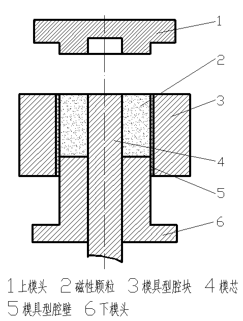
[0020] The magnetic particles are added into the hopper attached to the press, and the magnetic particles are added into the mold cavity by the feeding shoe, and the feeding shoe is connected with the hopper.

[0021] Such as figure 1 The mold cavity block and ...


PUM

PropertyMeasurementUnit
electrical resistanceaaaaaaaaaa

Abstract

The invention discloses an anisotropic multipole magnet ring forming mold system, and belongs to the field of magnetic material production. The anisotropic multipole magnet ring forming mold system comprises a multipole magnet ring forming mold, and further comprises a plurality of coil windings and an RC charge-discharge circuit, wherein the coil windings are wound on a plurality of magnetic poles in a cavity block of the multipole magnet ring forming mold, and are connected with the RC charge-discharge circuit. According to the anisotropic multipole magnet ring forming mold system, due to the fact that high currents are instantly generated by the RC charge-discharge circuit, the coil windings with the small number of turns can generate magnetic fields which are large enough, magnetic powder particles can carry out directional arrangement through the magnetic fields generated by the coil windings, and conditions are created for implementation of automatic extrusion of anisotropic multipole magnet rings and improvement of magnetic performance of the anisotropic multipole magnet rings.

Description

technical field [0001] The invention relates to a magnetic material production device, in particular to an anisotropic multi-pole magnetic ring forming mold system. Background technique [0002] Multi-pole magnetic rings are widely used in permanent magnet synchronous motors, permanent magnet stepper motors, instruments, timers, sensors, microwave devices, electronic devices and other fields. Compared with isotropic magnetic rings, anisotropic multi-pole magnetic rings It has the advantages of high magnetic performance and high cost performance. Anisotropic magnetic materials need to provide a magnetic field to align and orient the magnetic material particles during compression molding. The higher the degree of orientation of the magnetic material particles, the better the magnetic properties of the magnetic material and the higher the magnetic field strength generated. In order to obtain high magnetic properties, the orientation magnetic field must have sufficient strength...

Claims


Application Information

Patent Timeline
Patent Type & Authority Applications(China)
IPC IPC(8): B22F3/03B22F5/10H01F41/02
Inventor 丁世瑜
Owner 丁世瑜
Why Eureka
Try Eureka