Machine for implanting main bolts of nuclear power plant reactor and method for implanting bolts
A technology for nuclear power plant reactors and main bolts, applied in metal processing, metal processing equipment, manufacturing tools, etc., can solve problems such as large impact force, unstable load, and large error, and achieve the ability to eliminate alignment errors and smooth initial introduction , Reduce the effect of pressure and impact
- Summary
- Abstract
- Description
- Claims
- Application Information
AI Technical Summary
Problems solved by technology
Method used
Image
Examples
Embodiment 1
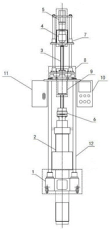
[0040] Such as figure 1 As shown, the implanter for the main bolt of the nuclear power plant reactor includes a base 1 and a drive assembly, a bracket 12 is arranged between the base 1 and the drive assembly, the bottom end of the bracket 12 is fixed on the base 1, and the top end of the bracket 12 is fixed There is an adaptive centering component 8, and a guide component 7 is arranged above the self-adaptive centering component 8, and the two ends of the guide component 7 are respectively connected with the self-adaptive centering component 8 and the drive component, and the bottom end of the self-adaptive centering component 8 A control box 11 is fixed, and the control box 11 is fixed on the bracket 12. The bottom end of the drive assembly is connected with a ball screw 3, and the ball screw 3 is fitted with a load balancer assembly 9. The load balancer assembly 9 is fixed and passes through the After adapting to the centering component 8, it is arranged inside the bracket 1...
Embodiment 2
[0042] Such as Image 6 As shown, on the basis of Embodiment 1, the load balancer assembly 9 includes a spring sleeve 21 and a lead screw nut 16 and a spring preloaded nut seat 24 arranged at both ends of the spring sleeve 21, and the lead screw nut 16 is arranged on the spring preloaded nut seat 24. Just above the tightening nut seat 24, and one end of the lead screw nut 16 and the spring preload nut seat 24 are all arranged inside the spring sleeve 21; 16 and the spring preloaded nut seat 24, a spring 20 is arranged between the spring sleeve 19 and the leading screw 3, the spring sleeve 19 is slidably matched with the inner wall of the spring sleeve 21, and the bottom end of the spring 20 is connected to the spring preloaded nut seat 24. The top is in contact, and a sensor 18 is arranged between the spring sleeve 19 and the screw nut 16. , spring sleeve 19, spring 20 and spring preload nut seat 24. The spring sleeve 21 is the basic part of the bearing spring 20. The spring...
Embodiment 3
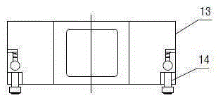
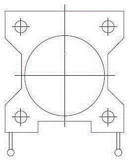
[0044] figure 2 is the front structure diagram of base 1, image 3 is its top view, Figure 4 It is a bottom view. On the basis of the above-mentioned embodiment, the circular through hole with a diameter of φ can make the base 1 pass through the main bolt and sit on the top cover. The base 1 comprises a body 13 and a retractable quick positioning stop pin 14 arranged on the side wall of the body 13, and the positioning stop pin 14 fixes the body 13 and the reactor top cover, from Figure 4 It can be seen that there are five electromagnetic coils 15 inlaid on the bottom of the base 1, four of which are respectively distributed on the four corners of the bottom surface of the body 13, and another electromagnetic coil 15 is arranged on the center line of the bottom surface of the body 13. A circular through hole with a diameter of φ is arranged at the top center of the body 13 , the through hole runs through the body 13 , and the bottom end of the bracket 12 is fixed to the t...
PUM
 Abstract
Description
Claims
Application Information
 - R&D
- Intellectual Property
- Life Sciences
- Materials
- Tech Scout
- Unparalleled Data Quality
- Higher Quality Content
- 60% Fewer Hallucinations
Browse by: Latest US Patents, China's latest patents, Technical Efficacy Thesaurus, Application Domain, Technology Topic, Popular Technical Reports.
© 2025 PatSnap. All rights reserved.Legal|Privacy policy|Modern Slavery Act Transparency Statement|Sitemap|About US| Contact US: help@patsnap.com


