Loader and bucket loading operation control method thereof

A control method and loader technology, applied to mechanically driven excavators/dredgers, etc., can solve problems such as low efficiency, and achieve the effects of reducing energy consumption, continuous operation, and reducing frictional resistance

Active Publication Date: 2014-03-05
GUANGXI LIUGONG MASCH CO LTD
View PDF6 Cites 16 Cited by
  • Summary
  • Abstract
  • Description
  • Claims
  • Application Information

AI Technical Summary

Problems solved by technology

[0003] The object of the present invention is to provide a loader shoveling operation control method with high shoveling efficiency and a loader corresponding to the method in view of the low efficiency of the existing loader when shoveling materials

Method used


Image

  • Loader and bucket loading operation control method thereof
  • Loader and bucket loading operation control method thereof
  • Loader and bucket loading operation control method thereof

Examples


Embodiment 1

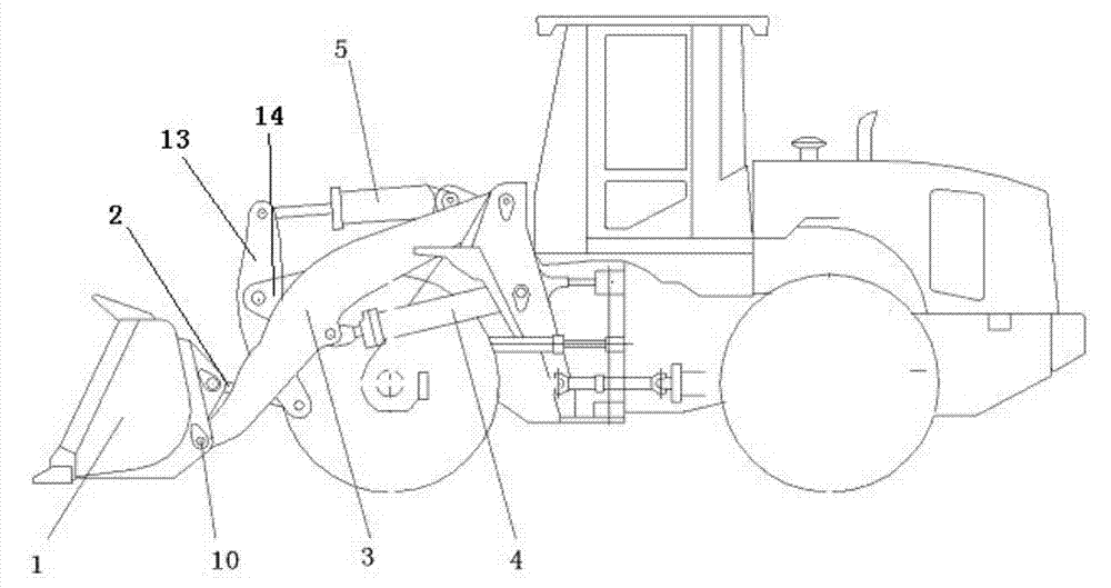
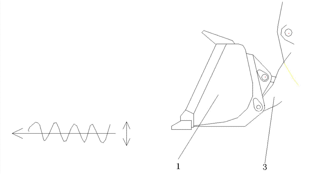
[0022] Such as figure 1 As shown, the loader includes a bucket 1, a bucket connecting rod 2, a bucket rocker arm 13, a boom 3, a boom cylinder 4, and a bucket cylinder 5, and the front of the two booms passes through a box-shaped connecting part 14 Fixed connection, the front end of the boom 3 is hinged with the bucket through the bucket rotation pin 10, the rear end of the boom 3 is hinged with the frame through the boom rotation pin, one end of the boom cylinder 4 is hinged with the boom, and the other end Hinged with the vehicle frame; one end of the bucket cylinder 5 is hinged with the vehicle frame, the other end is connected through the bucket rocker arm 13, the middle part of the bucket rocker arm 13 is hinged with the box-shaped connecting part 14, and the other end of the bucket rocker arm 13 is passed through The bucket connecting rod 2 drives the bucket 1 to rotate around the hinge pin of the bucket and the boom. The expansion and contraction of the boom oil cylind...

Embodiment 2

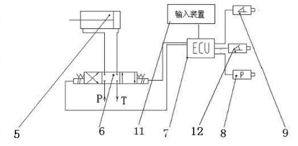
[0028] Compared with the technical solution in embodiment 1, the difference of the technical solution in this embodiment lies in the electronic control device for controlling the solenoid valve and the control of the solenoid valve. Such as Figure 4 As shown, the electronic control device is composed of a controller 7 and an input device 11. The controller 7 is used to send a control signal to the solenoid valve 6 to make the solenoid valve 6 act according to the set frequency and amplitude. The input device 11 is connected to the controller 7. It is used to input signals to the controller to make the controller select the corresponding control signal and send it to the solenoid valve. The input device can be a plurality of associated button switches or knob switches. The position and control of the knob of each button switch or each knob switch A signal sent by the controller to the solenoid valve corresponds to a frequency and amplitude of bucket swing. The manual control ...


PUM


Abstract

The invention relates to a loader and a bucket loading operation control method thereof, in order to solve the problem that existing loaders are low in efficiency when used for bucket loading of materials. According to the bucket loading operation control method of the loader, when a bucket is inserted into materials for excavation operation, flow direction of hydraulic oil in a driving oil circuit of a rotating bucket oil cylinder of the loader is controlled to enable the bucket to rotate and swing up and down around a bucket hinge pin shaft according to preset swing frequency and amplitude. The loader is characterized in that an electromagnetic valve for changing the flow direction of the hydraulic oil is arranged on the driving oil circuit of the rotating bucket oil cylinder. When the bucket is inserted into the bucket loading materials, the bucket is enabled to rotate and swing according to the preset frequency and amplitude, so that certain gap is enabled to be formed between the bottom surface of the bucket and the excavated materials in the excavation process so as to reduce frictional resistance between the materials and the bucket during excavation; meanwhile, continuity of the excavated materials can be interrupted by swing, frictional resistance between the materials in the bucket and the inner wall of the bucket is reduced, continuous operation of the excavation process is realized, and loading operation efficiency is improved while energy consumption is lowered.

Description

technical field [0001] The invention relates to a loader, in particular to a method for controlling the shovel loading operation of the loader and the loader. Background technique [0002] The usual operation method of a loader in shoveling operations is that the operator steps on the engine accelerator to the maximum, and the traction generated by the tires and the ground drives the whole machine to drive the bucket into the pile, but as the depth of the bucket inserted into the material Increase, the contact surface between the bucket and the material is getting bigger and bigger, so the friction between the bucket and the material is also increasing synchronously, until the resistance of the pile is equal to the traction force, the machine is forced to stop, but at this time there is no material in the bucket of the loader Filled with material. In order to fill the bucket with materials, the operator lifts the boom slightly by operating the handle at this time, and the m...

Claims


Application Information

Patent Timeline
Patent Type & Authority Applications(China)
IPC IPC(8): E02F3/42
Inventor 蔡登胜初长祥罗维李群华
Owner GUANGXI LIUGONG MASCH CO LTD
Why Eureka
Try Eureka