
MD190 switch cabinet

An MD190, switchgear technology, applied in the field of control devices, can solve the problems of inconvenient mass production, inconsistent modules of switchgear, inflexible design, etc., and achieve the effects of easy mass production, flexible design and simple structure

Inactive Publication Date: 2014-03-05
KUNSHAN ZHENHONG ELECTRONICS MACHINERY
View PDF6 Cites 2 Cited by
  • Summary
  • Abstract
  • Description
  • Claims
  • Application Information

AI Technical Summary

Problems solved by technology

[0003] The modulus of each component of the existing switchgear is not uniform, especially the beam parts are not common parts, so it is not convenient for mass production and the design is not flexible

Method used


Image

  • MD190 switch cabinet
  • MD190 switch cabinet
  • MD190 switch cabinet

Examples


Embodiment 1

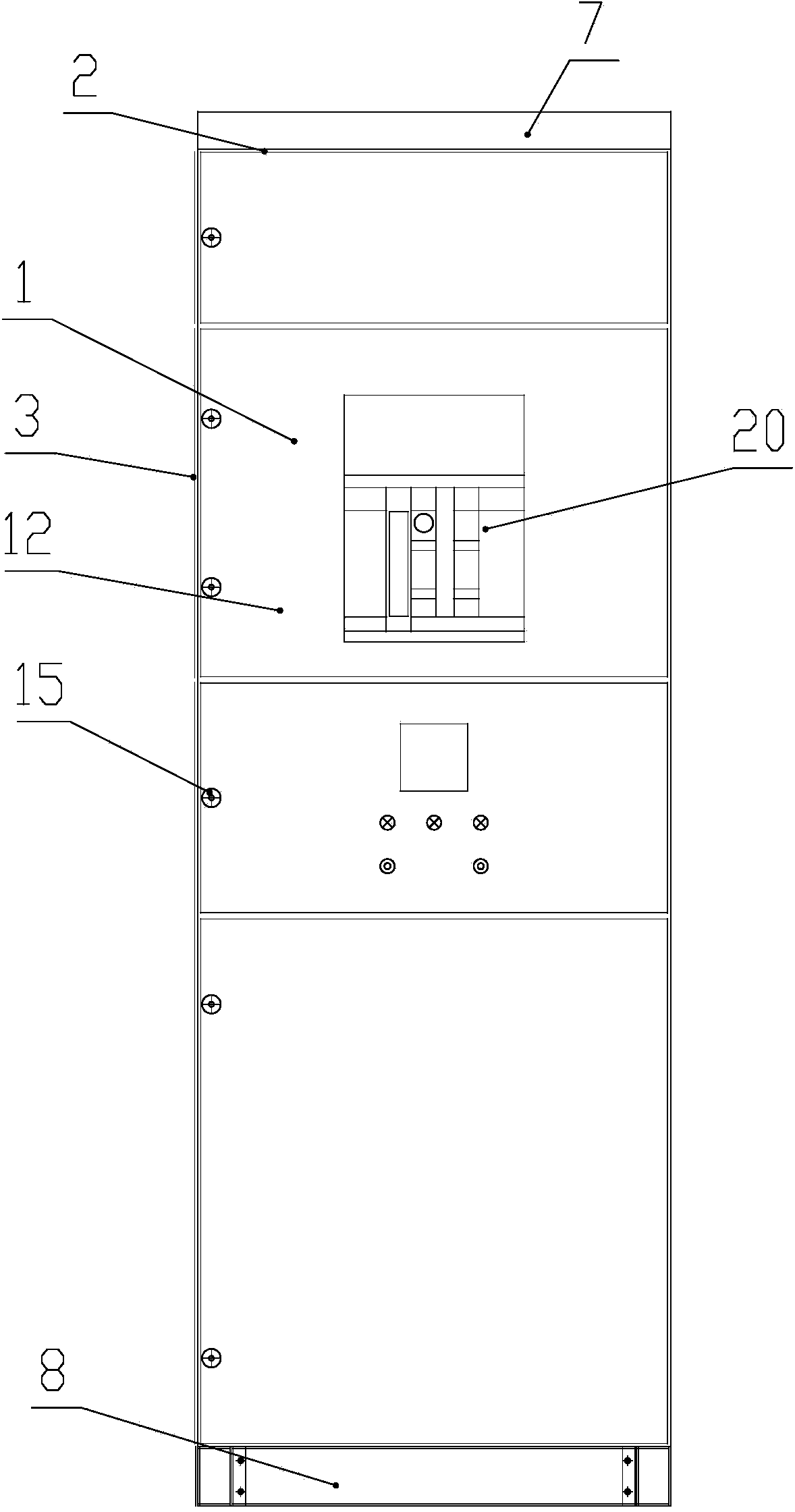
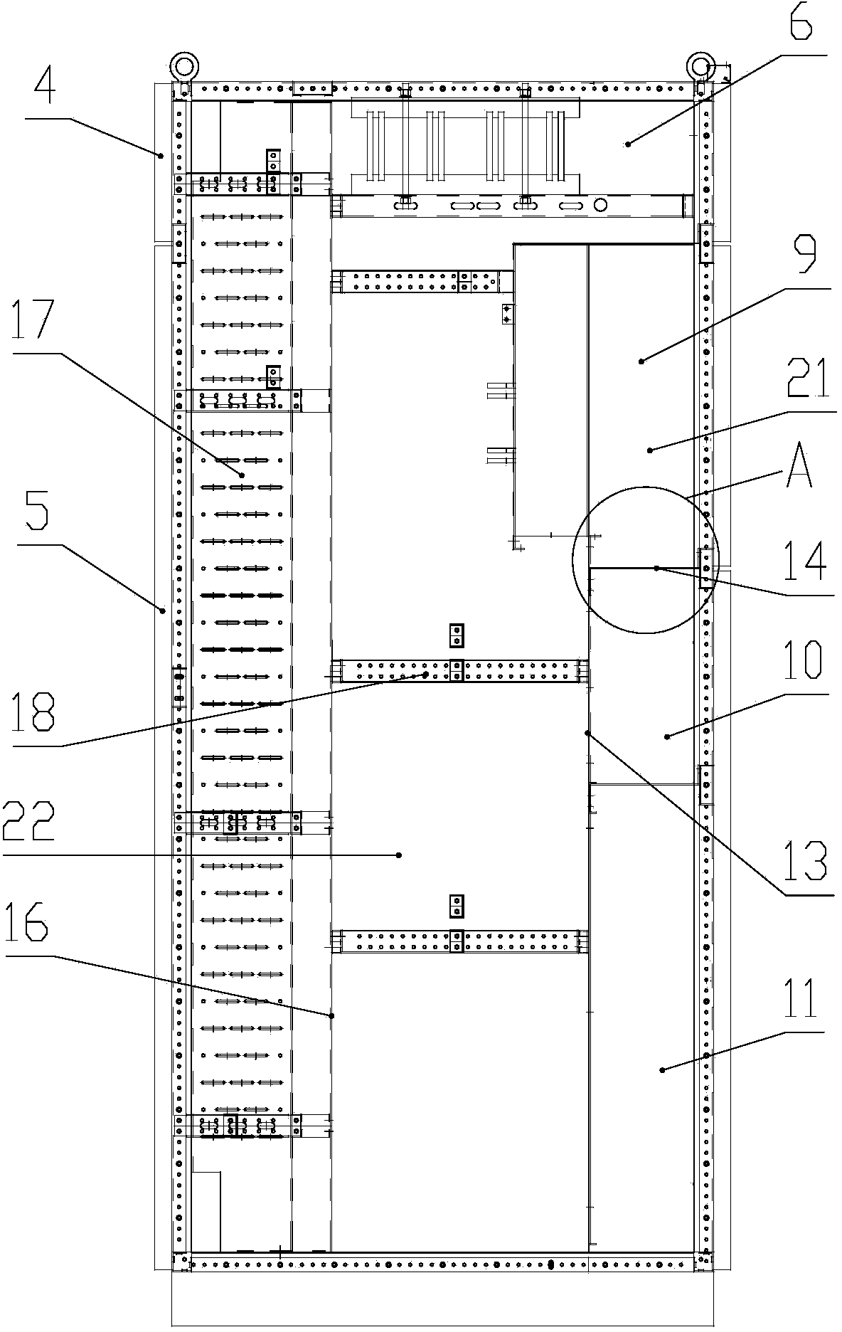
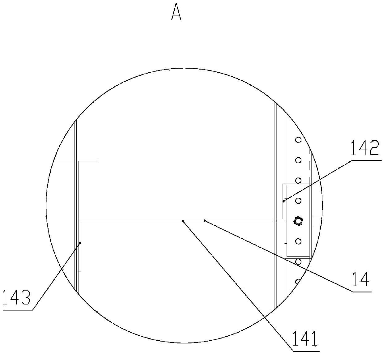
[0038] Figures 1 to 4 It is a schematic structural diagram of the MD190 switchgear provided in this embodiment. As shown in the figure, the MD190 switch cabinet includes a cabinet body 1, and the cabinet body 1 is surrounded by a top plate 2, left and right side plates 3, a rear upper cover plate 4 and a rear sealing plate 5. The busbar room 6 is set on the upper part. The brow 7 of the MD190 switchgear is red, and the internal electrical component mounting plate and bottom plate are orange. The dangerous area is very eye-catching and it is not easy to misuse. The bottom periphery of the cabinet body 1 is provided with a bottom frame 8, and the height of the bottom frame 8 is 95 mm.

[0039] Inside the cabinet body 1 are respectively a functional area 21 , a flowback area 22 and a cable room 17 from front to back. A plurality of functional chambers are provided in the functional area 21 , and the functional chambers in this embodiment are a circuit breaker chamber 9 , an i...


PUM


Abstract

The invention discloses an MD190 switch cabinet, and relates to the technical field of control devices, aiming to solve the problems that an existing MD190 switch cabinet is inconvenient for batch production, copper bars are not firm to install and the like. The MD190 switch cabinet comprises a cabinet body which is surrounded by a top plate, a left side plate, a right side plate, a rear upper cover plate and a rear seal plate, and is internally provided with a functional zone, a return discharge zone and an electric cable chamber from front to back, wherein the functional area is internally provided with a plurality of functional chambers; an electric cable chamber is formed among the rear upper cover plate, the rear seal plate as well as a baffle plate arranged at the rear part of the cabinet body; a plurality of support cross beams are arranged between the baffle plate and the plurality of functional chambers; the moduli of the support cross beams are equal to those of other parts of the switch cabinet. The moduli of the support cross beams in the MD190 switch cabinet disclosed by the invention are equal to those of other parts of the switch cabinet, and the MD190 switch cabinet can act as a universal element, is flexible to design, and is convenient for batch production.

Description

technical field [0001] The invention relates to the technical field of control devices, in particular to an MD190 switch cabinet. Background technique [0002] The switch cabinet is a kind of electrical control equipment. The outside line first enters the main control switch in the cabinet, and then enters the sub-control switch. Each branch is set according to its needs, such as instruments, automatic control devices, motor magnetic switches, various AC contactors, etc. [0003] The modulus of each part of the existing switchgear is not uniform, especially the beam parts are not common parts, so it is not convenient for mass production and the design is not flexible. Contents of the invention [0004] One object of the present invention is to provide a MD190 switchgear with flexible structure and convenient mass production. [0005] Another object of the present invention is to propose an MD190 switchgear in which the functional chambers are isolated from each other and ...

Claims


Application Information

Patent Timeline
Patent Type & Authority Applications(China)
IPC IPC(8): H02B1/30H02B1/56
Inventor 吴存林吴浩
Owner KUNSHAN ZHENHONG ELECTRONICS MACHINERY
Learn More