High-voltage direct-current breaker

A DC circuit breaker, high-voltage DC technology, applied in circuit devices, emergency protection circuit devices for limiting overcurrent/overvoltage, emergency protection circuit devices, etc. Breaking speed influence and other issues, to achieve the effect of rapid topology breaking, low manufacturing difficulty and high reliability

Active Publication Date: 2014-03-05
INST OF ELECTRICAL ENG CHINESE ACAD OF SCI
View PDF8 Cites 59 Cited by
  • Summary
  • Abstract
  • Description
  • Claims
  • Application Information

AI Technical Summary

Problems solved by technology

Different from the AC system, the current of the DC system does not have a natural zero-crossing point, so the natural zero-crossing point of the current cannot be used in the DC system like the AC system. Therefore, the breaking of the DC current has always been a problem worth studying. Subject
However, when the capacitance value is large, the breaking speed will be affected
[0006] ABB's patent (WO2011141054A1) proposes a hybrid circuit breaker technology, in which a mechanical switch and a power electronic full-control device are connected in series on the main path, and the other bypass is composed of a voltage limiting device and a crimping IGBT connected in parallel, when a fault current is detected , the crimping IGBTs on the bypass are all turned on, and then the power electronic full-control device on the main path is disconnected, and the mechanical switch is also turned off. After the mechanical switch is completely turned off, the crimping IGBT is turned off, and the voltage limiting device is connected. The circuit suppresses the short-circuit current. This kind of circuit breaker has a fast breaking speed, but the sum of the withstand voltage of the crimped IGBTs of the entire bypass must be greater than the initial voltage of the DC transmission line. This requires a large number of crimped IGBTs in series, resulting in the entire DC circuit breaker. higher cost
[0007] Moreover, the main circuits of the above two patents must use full-control switching devices in series with mechanical switches, resulting in large conduction losses in normal conditions.

Method used


Image

  • High-voltage direct-current breaker
  • High-voltage direct-current breaker
  • High-voltage direct-current breaker

Examples


Embodiment 1

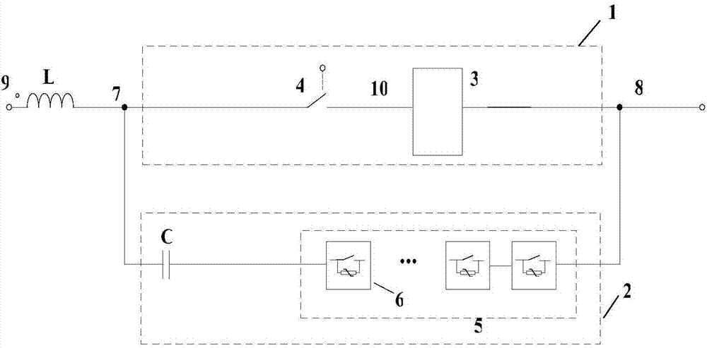
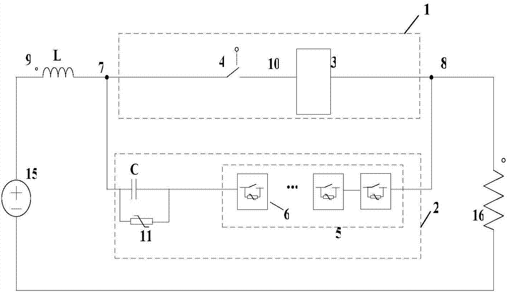
[0056] figure 2 Shown is Example 1 of the present invention. like figure 2 As shown, the DC power supply 15 is an analog converter station, and the inductance L is a current-limiting reactor built in the analog converter station. One end of the inductance is connected to the positive pole 9 of the converter station, and the other end of the inductance is connected to the first outlet of the DC circuit breaker. Terminal 7 connection. Resistor 16 is a short-circuit simulation resistor. The basic structure of the DC circuit breaker topology of the present invention is composed of an initial current path 1 and a fault current blocking path 2 . The first lead-out terminal of the initial current path 1 is connected to the first lead-out terminal of the fault current blocking path 2 as the first lead-out terminal 7 of the DC circuit breaker is connected to the external line, and the second lead-out terminal of the initial current path 1 is connected to the fault current resistan...

Embodiment 2

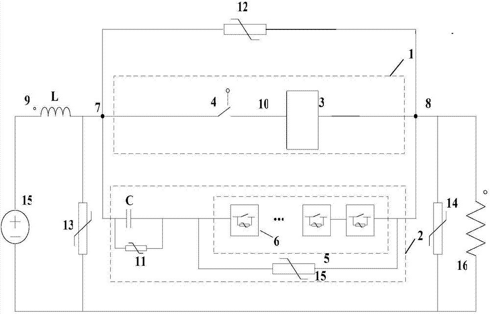
[0062] image 3 Shown is Example 2 of the present invention. like image 3 As shown, two series-connected voltage limiters 13 and 14 are connected in parallel at both ends of the initial current path 1, a voltage limiter 12 is connected in parallel at both ends of the capacitor module C of the fault current blocking path 2, and the series part of the modular switching subunit 5 A voltage limiter 15 is connected in parallel at both ends. Between the first lead-out terminal of the initial current path 1 and the ground, and between the second lead-out terminal of the initial current path 1 and the ground, for overvoltage protection of various parts of the entire DC circuit breaker. It is also possible to selectively add voltage limiting devices at both ends of the place where protection is required.

Embodiment 3

[0064] Figure 4 Shown is Example 3 of the present invention. Figure 4 The medium voltage source 15 is the converter station, the resistor 16 is the short-circuit analog terminal, the inductance L is the current-limiting reactor of the analog converter station, one end of the inductance is connected to the positive pole 9 of the converter station, and the other end of the inductance is connected to the DC circuit breaker The first lead-out terminal 7 is connected. The fault current blocking path 2 in this embodiment is composed of a capacitor module C and a series part 5 of modular switching subunits.

[0065] Figure 4 The power electronic switch module 3 in the initial current path 1 adopts a semi-controlled device thyristor. The power electronic switch module 3 can also be composed of multiple thyristors connected in series. In this way, the conduction loss of the entire DC circuit breaker is lower when the DC grid is operating normally, but since the thyristor has no ...


PUM


Abstract

A high-voltage direct-current breaker is composed of an initial current path (1) and a fail current interdicting path (2). The initial current path (1) comprises at least one electric electronic switch module (3) and a mechanical switch (4), and the fail current interdicting path (2) comprises an initial capacitor (C) and a modular switching subunit series connection component (5). The modular switching subunit series connection component (5) is formed by connecting a plurality of sub units (6) in series. When a high-voltage direct-current electric transmission line fails, the opening and closing of a fail electric transmission line can be rapidly achieved.

Description

technical field [0001] The invention relates to a circuit breaker, in particular to a DC circuit breaker topology. Background technique [0002] Fast DC circuit breaker is one of the key equipment to ensure the stable, safe and reliable operation of DC power transmission and distribution system and DC grid system. Different from the AC system, the current of the DC system does not have a natural zero-crossing point, so the natural zero-crossing point of the current cannot be used in the DC system like the AC system. Therefore, the breaking of the DC current has always been a problem worth studying. topic. [0003] At present, there are usually two ways to break DC current. The first is a pure power electronic circuit breaker, such as patent CN102870181A, which can turn off power electronic devices with high power and directly break DC current. Although the solid-state circuit breaker manufactured by this principle can meet the requirements of the multi-terminal flexible DC...

Claims


Application Information

Patent Timeline
Patent Type & Authority Applications(China)
IPC IPC(8): H02H7/26H02H9/02
Inventor 韦统振朱晋肖立业
Owner INST OF ELECTRICAL ENG CHINESE ACAD OF SCI
Why Eureka
Try Eureka