Direct-current side charging method of modular multi-level converter

A modular multi-level, DC side charging technology, applied in the direction of power transmission AC network, can solve the problems of increasing cost and workload, and achieve the effect of wide application range, clear logic, simple and effective operation

Inactive Publication Date: 2014-03-05
RONGXIN POWER ELECTRONICS +1
View PDF3 Cites 18 Cited by
  • Summary
  • Abstract
  • Description
  • Claims
  • Application Information

AI Technical Summary

Problems solved by technology

The former requires that the AC side of the modular multilevel converter must be a normal operating active grid, while the latter requires additional devices, increasing costs and workload

Method used


Image

  • Direct-current side charging method of modular multi-level converter
  • Direct-current side charging method of modular multi-level converter
  • Direct-current side charging method of modular multi-level converter

Examples


Embodiment Construction

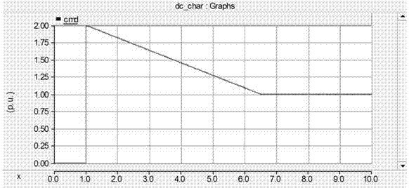
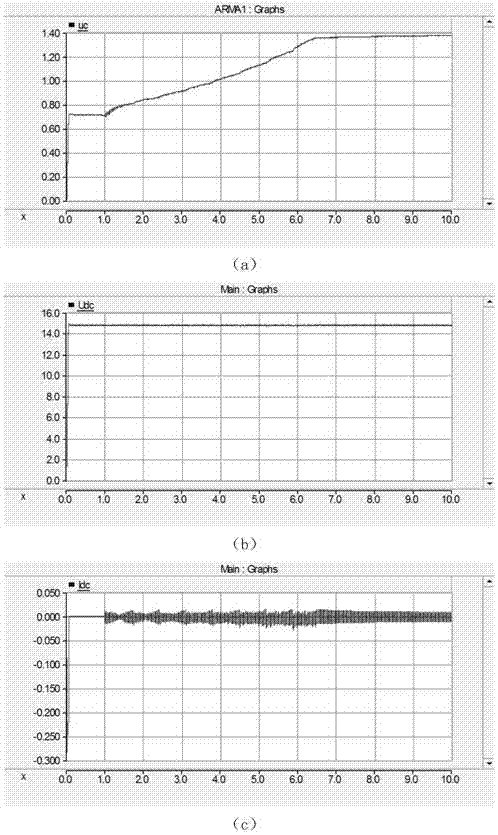
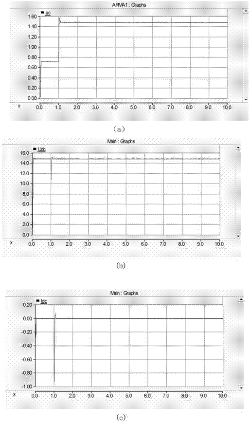
[0027] The technical solution of the invention will be described in detail below in conjunction with the accompanying drawings and specific implementation examples.

[0028] The modular multilevel converter of the present invention is a converter station in a flexible direct current transmission system, and is interconnected with other converter stations through a direct current line. The DC side of the modular multilevel converter includes one or two sets of isolating switches, the AC side is a passive network or an active network to be started, and the AC side includes an AC circuit breaker, an isolating switch and a commutation switch connected in series. The transformer, when the AC side is an active network, also includes a charging resistor, and a bypass switch is connected in parallel at both ends of the charging resistor. The DC side charging refers to the charging of the modular multilevel converter station from the DC side through the DC line.

[0029] In the presen...


PUM


Abstract

The invention discloses a direct-current side charging method of a modular multi-level converter. The direct-current side charging method of the modular multi-level converter comprises the steps that an alternating-current side disconnector of the modular multi-level converter is opened, and a circuit breaker of the modular multi-level converter is turned off; a system which is formed by converter stations except a converter station needing direct-current charging in a system runs normally; a direct-current side disconnector of the modular multi-level converter is closed, and non-control rectification precharge is carried out on the converter station needing direct-current charging through a direct-current line; after non-control rectification precharge is accomplished, the modular multi-level converter is unlocked through a method that the number of input sub-modules decreases progressively so that the modular multi-level converter can be continuously charged from the direct-current side until the capacitance and the voltage of the sub-modules reach preset values respectively; direct-current side charging of the modular multi-level converter is accomplished, and the modular multi-level converter is merged into the system to carry out operation. According to the direct-current side charging method of the modular multi-level converter, charging of the modular multi-level converter can be achieved on the situation that extra input is not increased, the phenomenon that a surge voltage and a surge current occur when the modular multi-level converter is directly unlocked after non-control rectification precharge of the direct-current side is accomplished is effectively avoided, and safety and stability of operation of a flexible direct-current power transmission system are improved.

Description

technical field [0001] The invention belongs to the technical field of power electronics, and in particular relates to a DC side charging method of a modularized multilevel converter. Background technique [0002] Modular multilevel converters are based on voltage source converters composed of fully-controlled turn-off devices, which have incomparable advantages over traditional DC transmission, and have become a hot research topic in the field of flexible DC transmission at home and abroad. An important development direction of direct current transmission. The start-up of the modular multilevel converter is the premise and basis for the normal operation of the system. If this link is not properly controlled, serious overvoltage and overcurrent will occur, and even cause system oscillation, affecting the normal operation of the AC system and endangering equipment and personal safety. . [0003] At present, there are two ways of pre-charging the sub-module capacitors of mod...

Claims


Application Information

Patent Timeline
Patent Type & Authority Applications(China)
IPC IPC(8): H02J3/36
CPCY02E60/60
Inventor 岳伟刘焕翁海清易荣秦健赵晓斌朱喆杨柳张海涛
Owner RONGXIN POWER ELECTRONICS
Why Eureka
Try Eureka