Method for positioning shell part in horizontal machining center and machining method

A technology of positioning method and processing method, which is applied in the direction of positioning devices, metal processing equipment, metal processing machinery parts, etc., can solve the problems of non-coincidence between the workpiece reference point and the rotary center of the worktable, long standby time, and deviation, and achieve reduction The effect of debugging scrap rate, improving efficiency, improving accuracy and reliability

Active Publication Date: 2020-04-21
SHAANXI FAST GEAR CO
View PDF8 Cites 14 Cited by
  • Summary
  • Abstract
  • Description
  • Claims
  • Application Information

AI Technical Summary

Problems solved by technology

[0006] The purpose of the present invention is to provide a positioning method and a processing method for shell parts in a horizontal machining center, which are used to solve the problems in the prior art that when the coordinate systems are manually established for each processing surface, the operation is cumbersome, the standby time is long, and the efficiency is low. ; The workpiece reference point does not coincide with the rotary center of the worktable, and there is a problem of deviation

Method used


Image

  • Method for positioning shell part in horizontal machining center and machining method
  • Method for positioning shell part in horizontal machining center and machining method
  • Method for positioning shell part in horizontal machining center and machining method

Examples


Embodiment 1

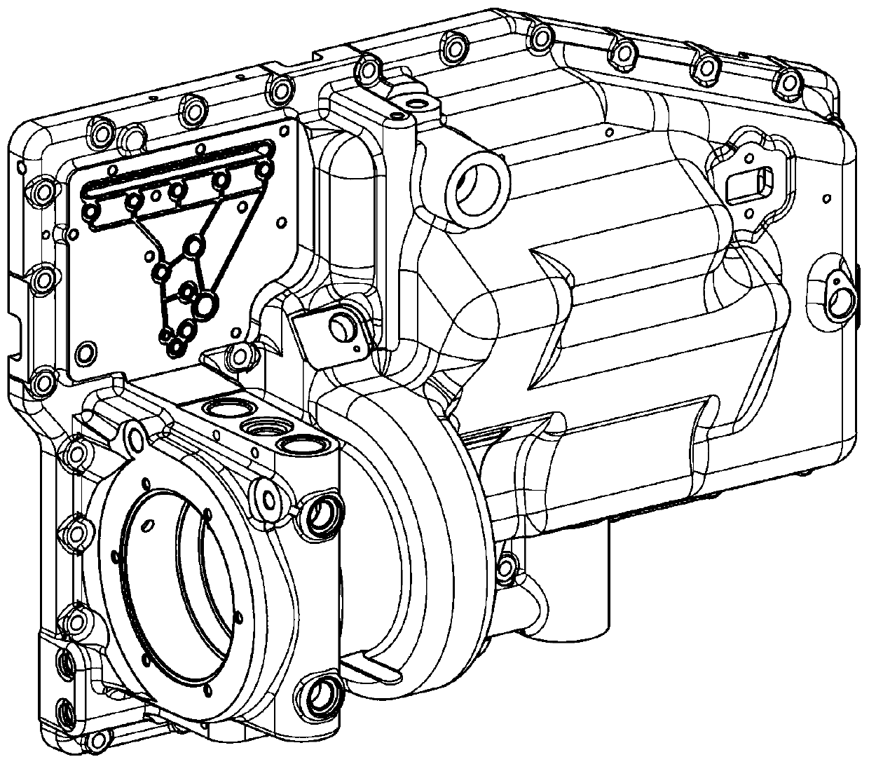
[0055] This embodiment specifically provides a positioning method taking the side cover shell as an example, which is used to determine the clamping position of the side cover shell on the machine tool workbench after the workbench is rotated, including the following steps:

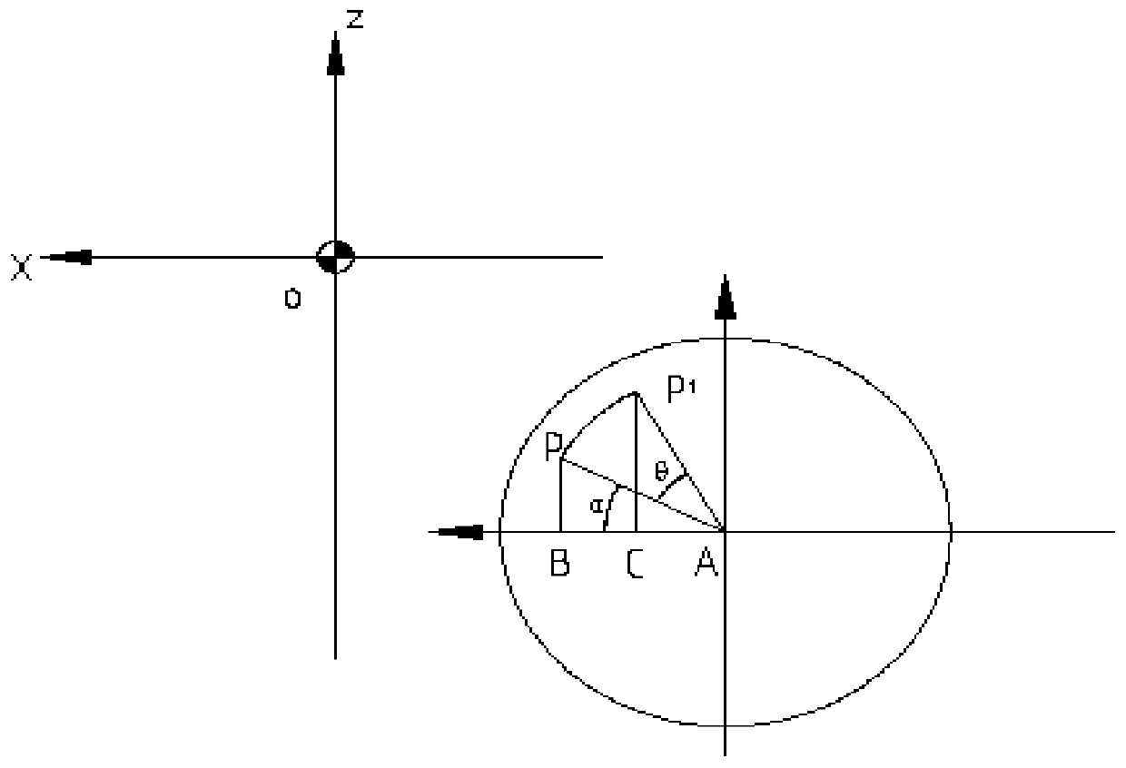
[0056] Step 1. Establish the machine tool coordinate system, and obtain the coordinates (a, b, c) of the center point A of the machine tool workbench and the coordinates (x, y, z) of the reference point P of the side cover shell in the machine tool coordinate system, The reference point P of the side cover housing is at any position on the machine tool table;

[0057] Step 2. According to the coordinates (a, b, c) of the turning center point A of the machine tool table described in step 1 and the coordinates (x, y, z) of the housing part reference point P, obtain the side cover housing reference point The distance between P and the turning center point A of the machine tool table and the angle ∝ between the...

Embodiment 2

[0080] This embodiment provides a processing method for shell parts on a horizontal machining center, including adopting the positioning method of the shell parts on the horizontal machining center of the present invention, and determining the position of the shell parts on the machine tool workbench after the workbench rotates. The clamping position, and then the processing method of production and processing, this method fixes the shell parts at any position on the machine tool table, and realizes the automatic offset of the coordinate origin during multi-directional processing.

[0081] This processing method specifically comprises the following steps:

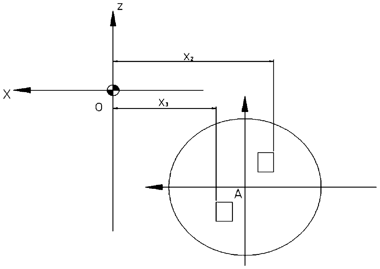
[0082] Step 1. Fix the shell parts at any position on the machine tool workbench, determine the reference point P of the shell parts in the position of the machine tool coordinate system; convert the origin of the G54 coordinate system according to the size of the drawing, and input the zero offset value of the origin of the...


PUM


Abstract

The invention discloses a method for positioning a shell part in a horizontal machining center and a machining method. The clamping position of the shell part on a machine tool workbench after the workbench rotates is determined, the shell part is machined, the method comprises the steps that the shell part is fixed at any position of the machine tool workbench, a user macro program of a numericalcontrol system is compiled, the user macro program of the numerical control system is input into a numerical control system of a machine tool, and automatic offset of the origin of coordinates duringmultidirectional machining is realized. According to the method for positioning the shell part, the coordinates of the original point of a workpiece coordinate system are obtained through automatic conversion of the macro program, the debugging time can be shortened, theoretical calculation has no error, the debugging rejection rate can be reduced, the cost is saved, and automatic offset of the coordinate original point during multidirectional machining can be achieved without clamping a workpiece datum point to a rotation center of the workbench.

Description

technical field [0001] The invention relates to the field of numerically controlled horizontal machining, in particular to a positioning method and a machining method for shell parts in a horizontal machining center. Background technique [0002] For shell parts, features in multiple orientations can be processed in one clamping on the horizontal machining center, that is, features in all directions except the top surface and bottom surface can be processed to avoid errors caused by multiple clamping. However, for horizontal plus multi-directional machining, in order to be intuitive and convenient for programming and calculation, the method of manually measuring and establishing the workpiece coordinate system at different machining angles is usually used at present. Before processing, level the fixture first, then find out the reference point on the fixture or the workpiece, and then calculate the zero offset value of the workpiece coordinate system corresponding to the B-a...

Claims


Application Information

Patent Timeline
Patent Type & Authority Applications(China)
IPC IPC(8): B23Q3/06
CPCB23Q3/06
Inventor 严鉴铂赵艳文史晓亮
Owner SHAANXI FAST GEAR CO
Why Eureka
Try Eureka