Mixed-mode multi-protocol serial interface driver

A serial interface and hybrid mode technology, applied in the direction of logic circuit connection/interface layout, etc., can solve the problem of no drive circuit

Inactive Publication Date: 2014-03-05
SUZHOU BATELAB MICROELECTRONICS
View PDF5 Cites 11 Cited by
  • Summary
  • Abstract
  • Description
  • Claims
  • Application Information

AI Technical Summary

Problems solved by technology

Therefore, an additional circuit needs to be placed to maintain the drive circuit is not currently used in a high-impedance state

Method used


Image

  • Mixed-mode multi-protocol serial interface driver
  • Mixed-mode multi-protocol serial interface driver
  • Mixed-mode multi-protocol serial interface driver

Examples


Embodiment Construction

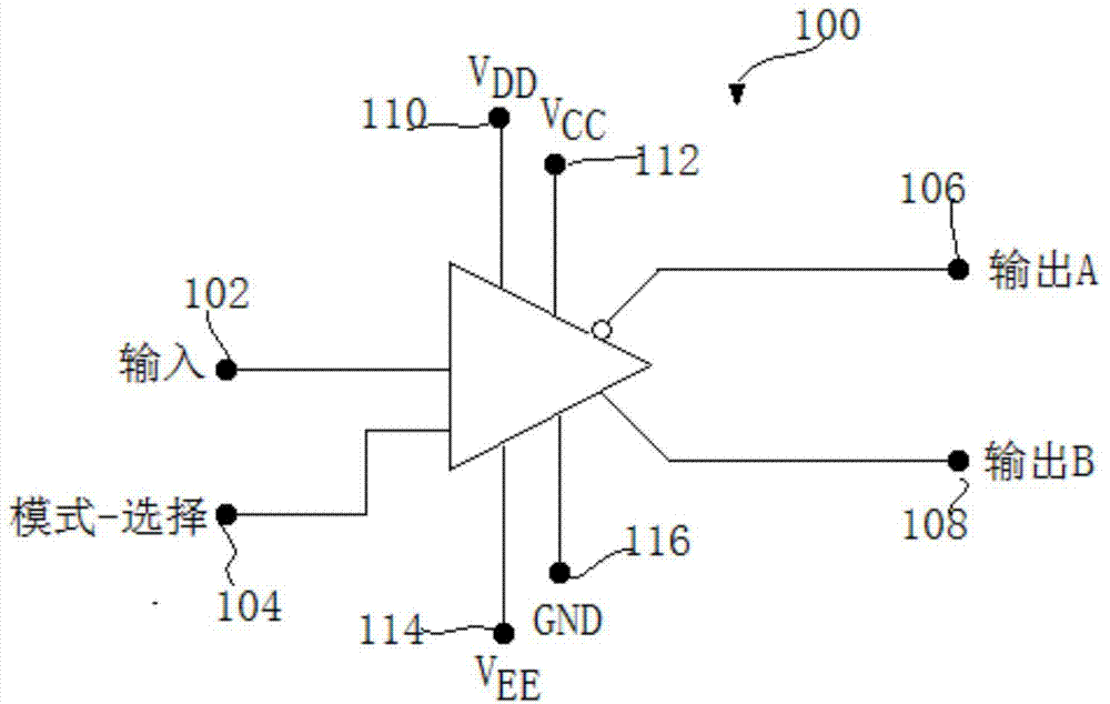
[0031] The present invention provides a mixed-mode multi-protocol serial interface driver whose function is to conform the output signal to an optional electrical interface standard. figure 1 depicts a serial interface driver block diagram. Output signals can be selected from the following CCITT / EIA standards: V.35, V.11 / RS-422, V.28 / RS-232, and V.10 / RS-423. The interface drive circuit 100 includes a circuit that can be used in voltage mode, current mode, or both modes, and also includes an output terminal 102, a mode selection output terminal 104, output terminals 106 and 108, and power supply terminals 110, 112, 114 and 116.

[0032] After terminal 102 accepts an input signal, output terminals 106 and 108 provide an inverted or non-inverted output signal, respectively. Thus, differential, or symmetrical, outputs may be provided for those interface standards that require such an output signal. The logic value of a differential output signal is determined by the voltage dif...


PUM


Abstract

Provided is a mixed-mode multi-protocol serial interface driver. The driver can work in the current mode or the voltage mode or work in the two modes at the same time. The driver comprises a circuit used for making an output signal conform to one of a series of selectable electrical interface standards including the CCITT / EIA standards V.35, V.11 / RS-422, V.28 / RS-232 and V.10 / RS-423. When the specific standard is selected for an input signal through mode selection, a proper portion in the circuit can start response. Part of the circuit can not be placed in a high-impedance state, and the part of the circuit is prevented from interfering with the portion, starting the response, of the circuit.

Description

Technical field: [0001] The invention relates to a serial communication between electronic devices. More specifically, the present invention relates to a mixed-mode multi-protocol serial interface driver. Background technique: [0002] Communication between electronic devices, such as computer processors, modems, network controllers, hard drives, and printers, is accomplished by sending information (eg, data and control signals) serially or in parallel. Serial communication transmits data sequentially through a single wire, while parallel communication transmits multiple pieces of data simultaneously through parallel wires. Although parallel communication is faster than serial communication, the significantly higher cost of parallel cables compared to serial cables limits the implementation of parallel communication between devices in close proximity, for example, a computer and a nearby printer. Therefore, most electronic communications are serial. [0003] Information i...

Claims


Application Information

Patent Timeline
Patent Type & Authority Applications(China)
IPC IPC(8): H03K19/0175
Inventor 李志鹏
Owner SUZHOU BATELAB MICROELECTRONICS
Why Eureka
Try Eureka