Pixel array with reduced sensitivity to defects

a technology of pixel array and defect sensitivity, which is applied in the field of semiconductor pixel array, can solve the problems of array non-operation, entire array cannot be used, so as to reduce the number of control lines, increase the yield of devices, and reduce the effect of impedance sta

Active Publication Date: 2012-09-04
CMOSIS
View PDF11 Cites 0 Cited by
  • Summary
  • Abstract
  • Description
  • Claims
  • Application Information

AI Technical Summary

Benefits of technology

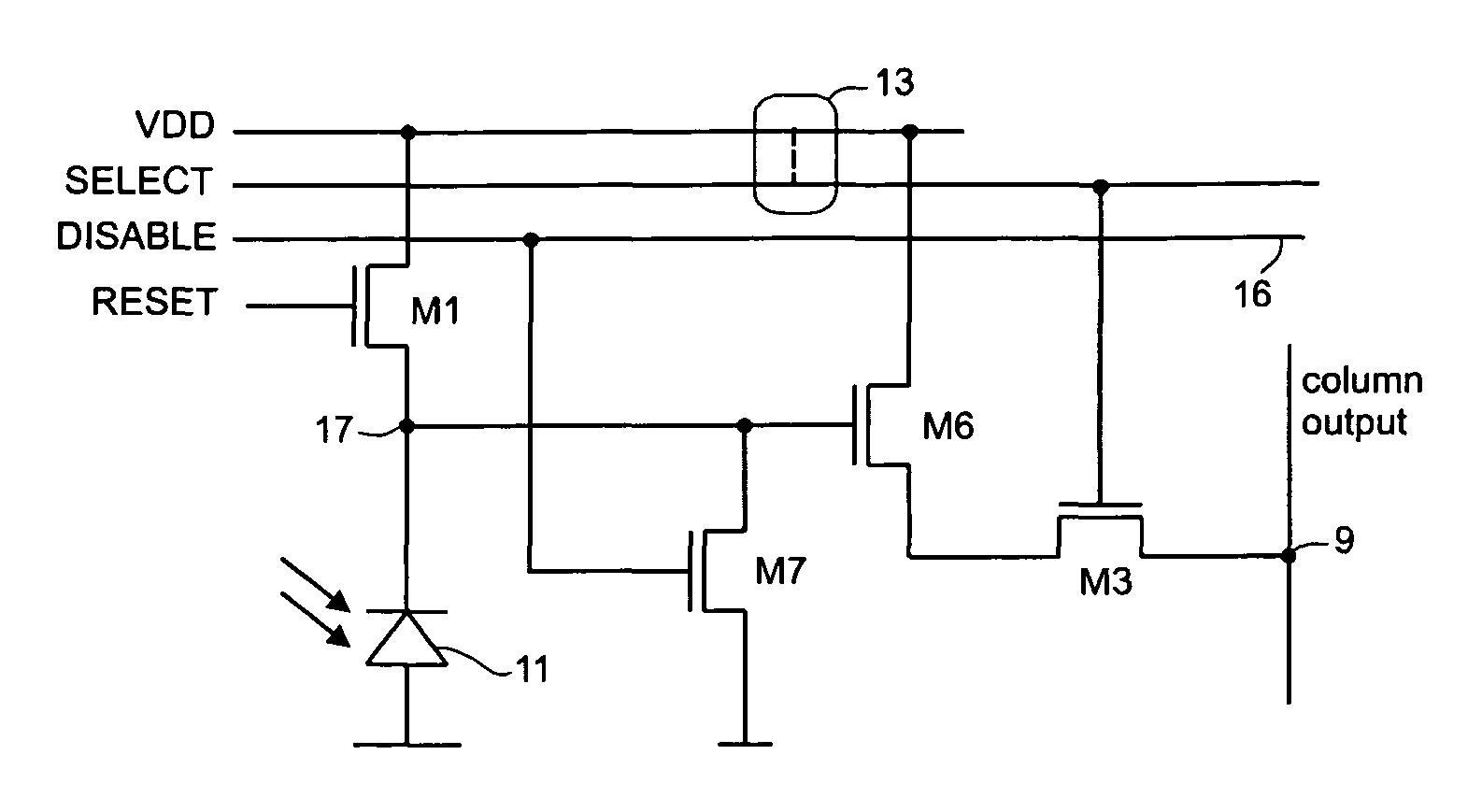
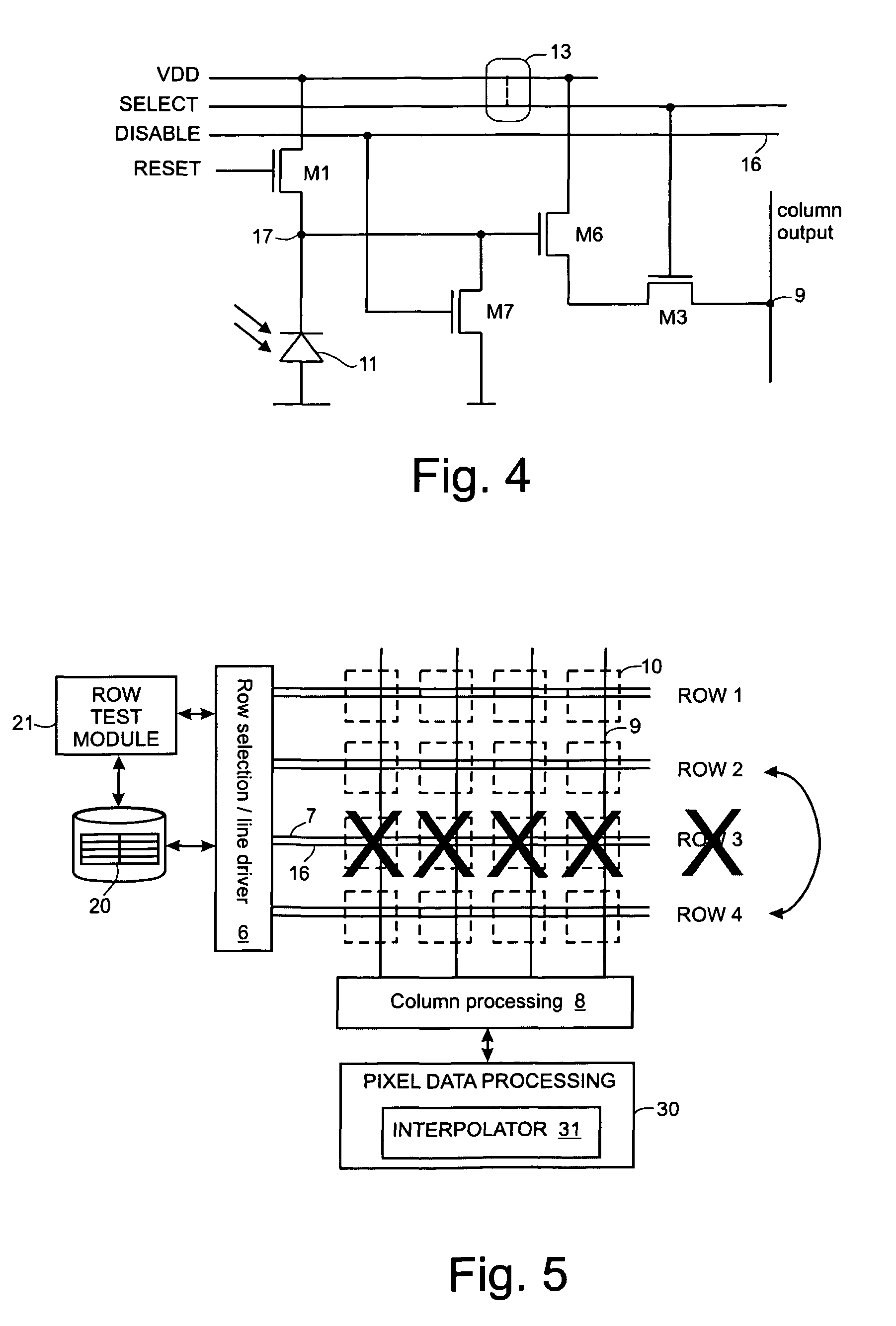
[0011]By putting the buffer amplifier (also known in some types of pixel sensors as a source-follower) into a high impedance state, that pixel is disabled. Other pixels in the same row will be similarly disabled. This allows other rows, which are defect-free, to remain operating as normal. This increases the yield of devices on a wafer, as devices with this type of defect can still be used.
[0012]One way of putting the buffer amplifier into a high impedance state is to provide a disable line for a row of pixels. Each pixel comprises a second switch having an input connected to the disable line. The second switch is operable in: a first state, in which the buffer amplifier is allowed to operate as a buffer amplifier; and, a second state in which the second switch ties the input of the buffer amplifier to ground, or a low voltage supply line. A disable line can be provided per row of pixels or a disable line can be provided for multiple (at least two) rows of pixels, with all pixels on the multiple rows sharing that disable line. This has an advantage of reducing the number of control lines in the array, but has a penalty that, in the case of a defect, the multiple rows of pixels sharing the disable line will be rendered non-operational. This can be concealed by suitable error-correction techniques, such as calculating values for the non-operational pixels by an interpolation calculation using pixel data values of operational lines.

Problems solved by technology

These errors can result from defects in the fabrication process.
Consequently, also for this defect, the entire array can not be used.
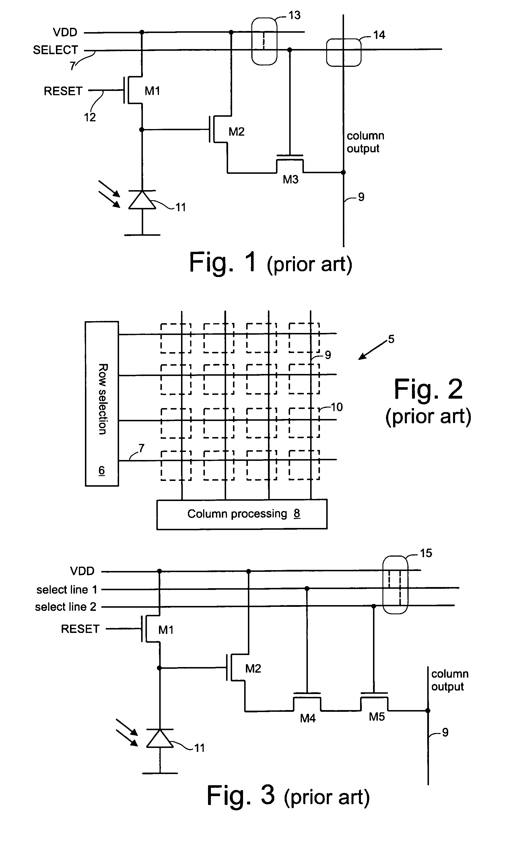
However, a defect which shorts both select lines to the supply line, shown as 15, will still render the array non-operational.
Such double short errors can occur at large defects on a wafer, such as defects of a few microns in size.

Method used


Image

  • Pixel array with reduced sensitivity to defects
  • Pixel array with reduced sensitivity to defects
  • Pixel array with reduced sensitivity to defects

Examples


Embodiment Construction

[0032]The present invention will be described with respect to particular embodiments and with reference to certain drawings but the invention is not limited thereto but only by the claims. The drawings described are only schematic and are non-limiting. In the drawings, the size of some of the elements may be exaggerated and not drawn on scale for illustrative purposes. Where the term “comprising” is used in the present description and claims, it does not exclude other elements or steps. Furthermore, the terms first, second, third and the like in the description and in the claims, are used for distinguishing between similar elements and not necessarily for describing a sequential or chronological order. It is to be understood that the terms so used are interchangeable under appropriate circumstances and that the embodiments of the invention described herein are capable of operation in other sequences than described or illustrated herein.

[0033]FIG. 4 shows an active pixel in accordanc...


PUM


Abstract

An array of active pixels comprises rows of pixels and row select lines for selecting rows of pixels. Each active pixel comprises a buffer amplifier for buffering an output of a photo-sensitive element. An output of the buffer amplifier can be selectively put into a high impedance state, by control of the input of the buffer amplifier, when there is a defect in the row select line for that pixel. This allows other rows, which are defect-free, to remain operating as normal. A disable line can be provided for a row of pixels and each pixel can have a switch connected to the disable line. Alternatively, a first supply line powers a row of pixels. Each pixel comprises a reset switch connected between a photo-sensitive element and the first supply line for resetting the photo-sensitive element. The array is configured such that, in the event of a defect in a row select line, the first supply line is set to ground, or a low voltage, and the reset switch is turned on to put the buffer amplifier into the high impedance state.

Description

FIELD OF THE INVENTION[0001]This invention relates to semiconductor pixel arrays for use in image sensors.BACKGROUND TO THE INVENTION[0002]It is known to manufacture image sensors using CCD technology or CMOS technology. One advantage of CMOS technology is that it allows additional devices to be fabricated directly alongside a photodiode on a semiconductor wafer. A conventional three transistor (3T) Active Pixel Sensor (APS), or active pixel, is shown in FIG. 1. A reset transistor M1 initialises the cathode of a photodiode 11 to a known voltage at the beginning of an image capture. After a reset, radiation incident on the photodiode generates a photocurrent which starts to integrated charge at the gate of a source-follower / buffer amplifier M2. At the end of an image capture, select transistor M3 is enabled to provide an output voltage which is dependent on the amount of charge stored at the gate of transistor M2.[0003]FIG. 2 shows an array 5 of pixels 10, each pixel 10 being of the ...

Claims


Application Information

Patent Timeline
Patent Type & Authority Patents(United States)
IPC IPC(8): H04N9/64H04N5/367H04N5/374
CPCH04N5/367H04N5/3745H04N5/374H04N25/68H04N25/77H04N25/76
Inventor MEYNANTS, GUY
Owner CMOSIS
Why Eureka
Try Eureka