Reset generator

Active Publication Date: 2013-04-04
ANALOG DEVICES INC
View PDF2 Cites 0 Cited by
  • Summary
  • Abstract
  • Description
  • Claims
  • Application Information

AI Technical Summary

Benefits of technology

[0007]a control circuit arranged to switch the depletion mode devi

Problems solved by technology

They may also be used to supply a reset signal in the event of power supply “brown out” or if a processor gets “hung” or otherwise stalled such that it is probable that its operation has beco

Method used


Image

  • Reset generator
  • Reset generator
  • Reset generator

Examples


Example

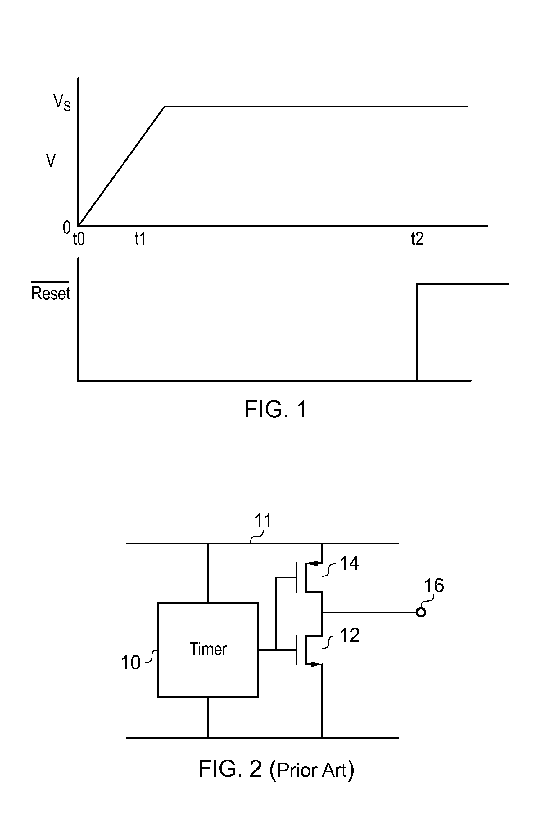
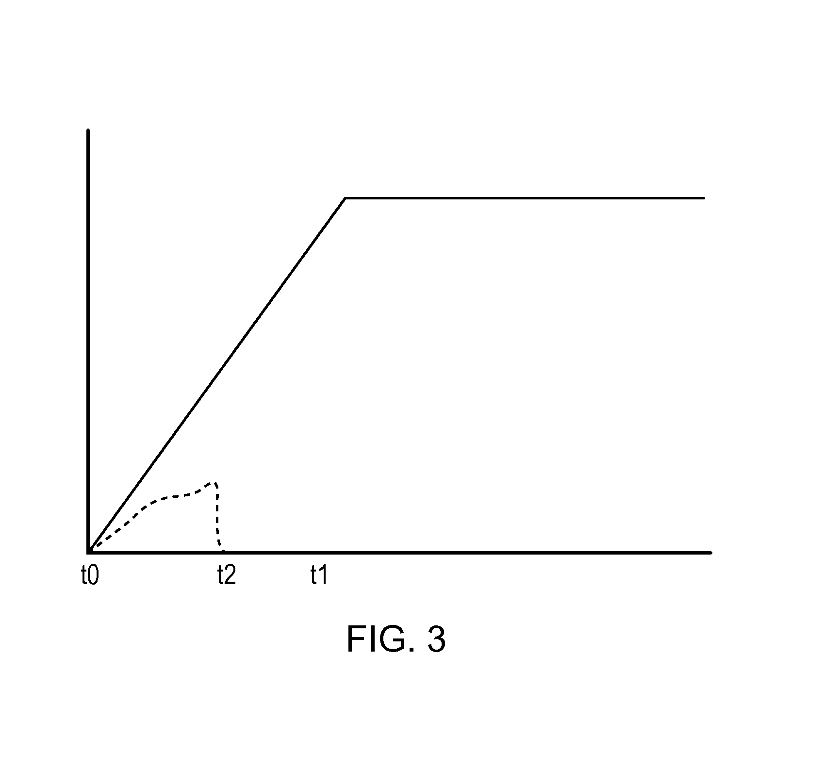
[0020]FIG. 1 shows the evolution with respect to time of the voltage supplied to a circuit at a switch on event, which will also be referred to as “power up”. It has been assumed, for simplicity, that the supply is made via an electrically controllable switch such that undesirable features such as contact bounce have been eliminated. Connection to the supply is initiated at time T0. However due to the finite impedance of the voltage supply and the inclusion of capacitive components in the circuit, the supply does not rise instantaneously to its final voltage Vs but instead ramps up during a period spanning T0 to T1. The ramp has been drawn as linear although it may in practice have a non-linear component. After T1 the supply voltage can be assumed to be stabilised.

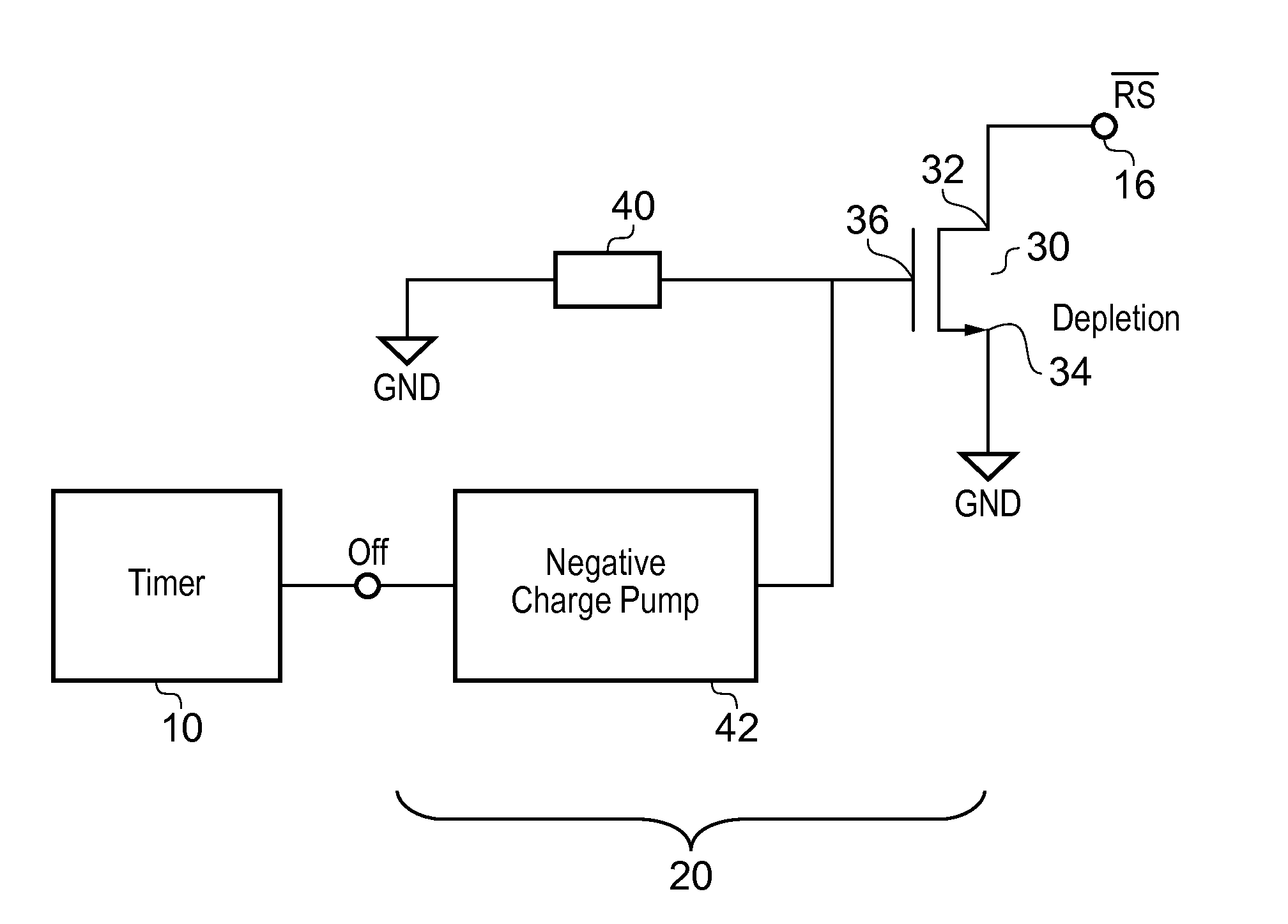
[0021]Electronic circuits including digital processors may power up in an undefined state. This may result in undesirable control signals being issued to components controlled by the processor. It is therefore known to pro...


PUM


Abstract

A reset circuit comprising: a first depletion mode device having a first terminal coupled to a node at a reset voltage and a second terminal for providing a reset signal to at least one device; and a control circuit arranged to switch the first depletion mode device into a high impedance state after a first predetermined period.

Description

FIELD OF THE INVENTION[0001]The present invention relates to a reset generator.BACKGROUND OF THE INVENTION[0002]Reset generators are used to apply a reset signal to processors and other circuits. Such a signal may be provided shortly after a circuit has powered up so as to ensure that it is in a known state. They may also be used to supply a reset signal in the event of power supply “brown out” or if a processor gets “hung” or otherwise stalled such that it is probable that its operation has become compromised.[0003]It is well recognised that an important aspect of the “reset” function is to avoid giving false reset signals to the processor. As a result the reset generator is generally designed to be robust in the presence of noisy supplies.[0004]A particularly difficult case is the state or evolution of the reset signal itself on initial power up of the reset circuit, especially when this coincides with device power up.SUMMARY OF THE INVENTION[0005]According to a first aspect of th...

Claims


Application Information

Patent Timeline
IPC IPC(8): H03K17/20
CPCG06F1/24H03K17/223H03K17/063
Inventor SPALDING, JR., GEORGE REDFIELDPEPPIETTE, ROGERO'LEARY, FINBARR CHRISTOPHER
Owner ANALOG DEVICES INC
Why Eureka
Try Eureka