Device for treating workpieces

A technology for workpieces, equipment, applied in the field of processing workpieces, capable of solving problems such as malfunctions, impairment of technical functions, workpiece cooling lubricants and debris contamination

Active Publication Date: 2014-03-05
DUERR ECOCLEAN GMBH
View PDF13 Cites 9 Cited by
  • Summary
  • Abstract
  • Description
  • Claims
  • Application Information

AI Technical Summary

Problems solved by technology

In addition, during chip machining, the workpiece becomes soiled with cooling lubricants and swarf
This can cause malfunctions during

Method used


Image

  • Device for treating workpieces
  • Device for treating workpieces
  • Device for treating workpieces

Examples


Embodiment Construction

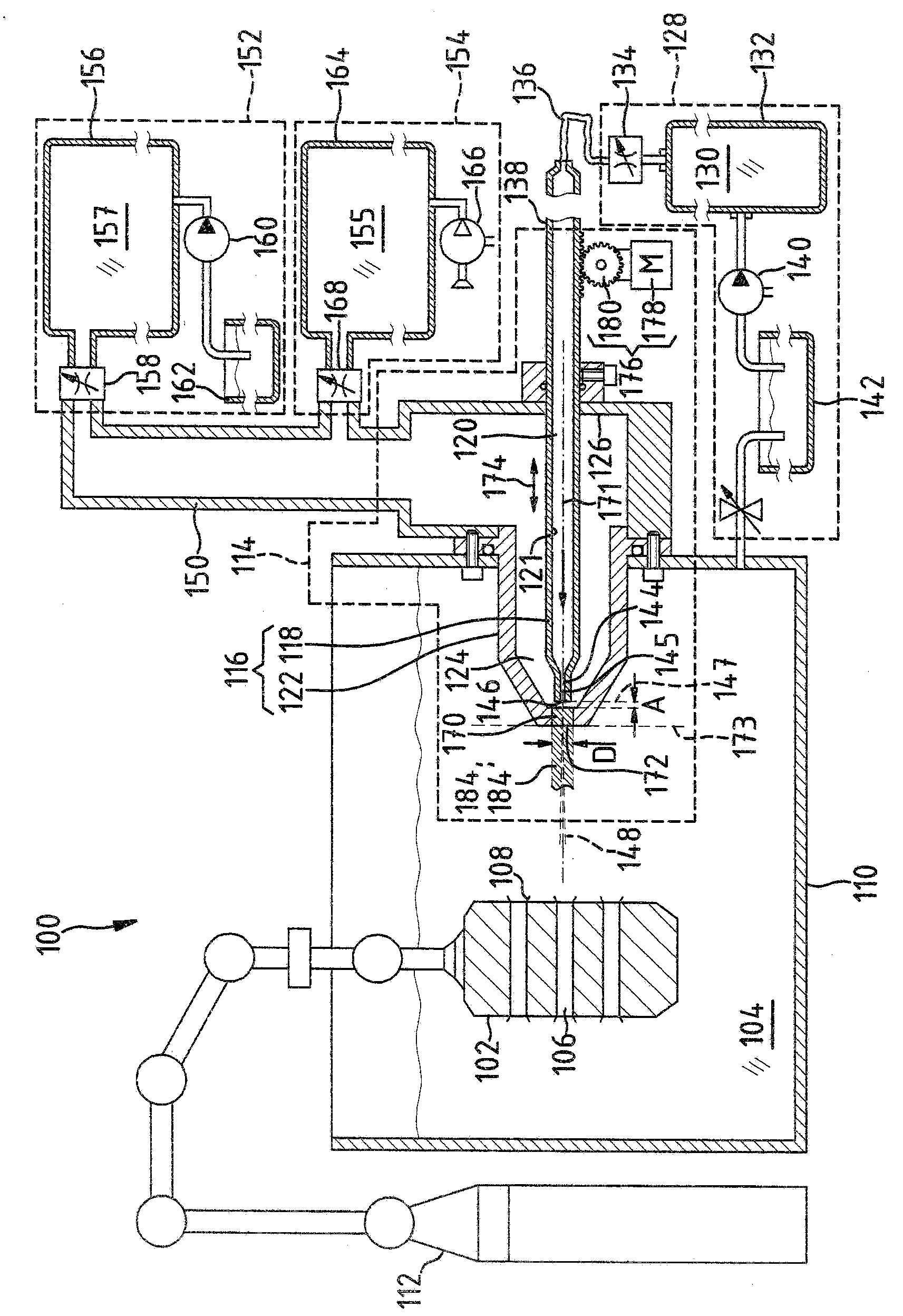
[0034] figure 1 A cleaning device 100 is shown for rinsing workpieces 102 in a liquid bath 104 . The cleaning device 100 is a processing device for a workpiece 102 in the form of an aluminum cylinder head in which a plurality of boreholes 106 are formed. In order to insert the drill hole, the workpiece 102 is machined in a machining center chip-cutting. In the cleaning device 100 the workpiece 102 is not only cleaned of dirt in the form of cooling lubricants and debris. The cleaning device 100 also enables the deburring of workpieces, that is to say the removal of burrs 108 on the workpiece 102 which originate from chip machining in the machining center.

[0035] The liquid tank 104 is located in the liquid container 110 . A handling robot 112 is present in the cleaning device 100 . The workpiece 102 can be accommodated in the cleaning device by the handling robot 112 and manipulated with three translational and three rotational degrees of freedom in the liquid tank 104 . ...


PUM


Abstract

The invention relates to a device (100) for treating, in particular for cleaning and/or deburring, workpieces (102), comprising a nozzle module (114) having a module body (116) comprising a nozzle chamber (120). The nozzle chamber (120) comprises at least one nozzle opening (146) for generating at least one high-pressure liquid stream (148) directed at a workpiece (102). The module body (116) comprises a further nozzle chamber (124) having at least one nozzle opening (172) for generating a low-pressure liquid stream (184, 184') running at least in sections along the high-pressure liquid stream (148) and contacting same. In the device is a mechanism (128) for feeding liquid (130) under high pressure into the one nozzle chamber (120) for generating the at least one high-pressure liquid stream (148) directed at the workpiece (102). The device comprises a mechanism (154) for selectively feeding liquid (157) under low pressure or gaseous liquid (155) into the further nozzle chamber (124).

Description

technical field [0001] The invention relates to a device for processing, in particular cleaning and / or deburring workpieces, with a nozzle module having a module body with a nozzle chamber with at least one nozzle for generating Nozzle opening for at least one high-pressure fluid jet directed at the workpiece, wherein the module body contains a further nozzle chamber with at least one nozzle for generating at least one jet extending at least in sections along the high-pressure fluid jet and resting against the Nozzle openings for a low-pressure fluid jet on a high-pressure fluid jet, wherein the device also includes a device for feeding fluid loaded with high pressure into the nozzle chamber for generating at least one high-pressure fluid jet. Background technique [0002] EP2252413B1 discloses such a device. [0003] Burrs are produced on the edges of grooves and drilled holes during chip machining of workpieces, such as engine components such as cylinder heads. In additi...

Claims


Application Information

Patent Timeline
IPC IPC(8): B08B3/02B08B3/10B24C1/08
CPCB08B3/102B08B3/02B24C1/083B05B1/00B05B9/00B08B3/04B08B5/02
Inventor 赫尔曼-约瑟夫·戴维埃贡·卡斯克诺伯特·克林克哈默
Owner DUERR ECOCLEAN GMBH
Why Eureka
Try Eureka