Screen printing device

A technology of screen printing and printing position, which is applied in screen printing, screen printing machine, printing, etc., and can solve the problems of increasing waste, increasing the cost of screen templates, etc.

Active Publication Date: 2014-03-05
YAMAHA MOTOR CO LTD
View PDF7 Cites 8 Cited by
  • Summary
  • Abstract
  • Description
  • Claims
  • Application Information

AI Technical Summary

Problems solved by technology

[0006] However, in the structure of Patent Document 1, since each print execution unit is vainly configured in a redundant structure, the waste increases.
That is, in the case of continuously producing the same type of substrate, it is necessary to make two screen templates provided with the same opening pattern, so the cost of the screen template increases
In addition, since solder needs to be prepared for each screen stencil, the amount of solder required for preparation becomes excessive, and costs are also required for handling (disposal, storage, etc.) of solder after production.
In addition, due to the redundant structure in which the same print execution units are combined on the left and right, it is necessary to secure a space for installing each print execution unit. Tendency to increase, such as conveyor belts

Method used


Image

  • Screen printing device
  • Screen printing device
  • Screen printing device

Examples


no. 3 approach

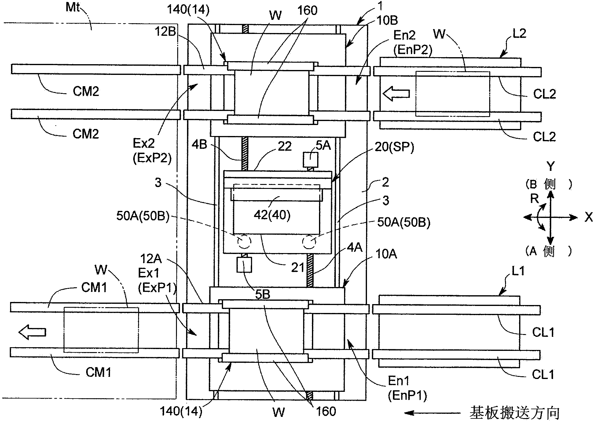
[0159] exist figure 1 In a general screen printing apparatus 1, for example, in the case of carrying out an out-and-out operation against a delay, if the common area is vainly deviated and the substrate support table 10B (10A) on the entry side is approached, the printing process is executed in the next process. The entry operation of the other substrate supporting table 10A ( 10B) may take time.

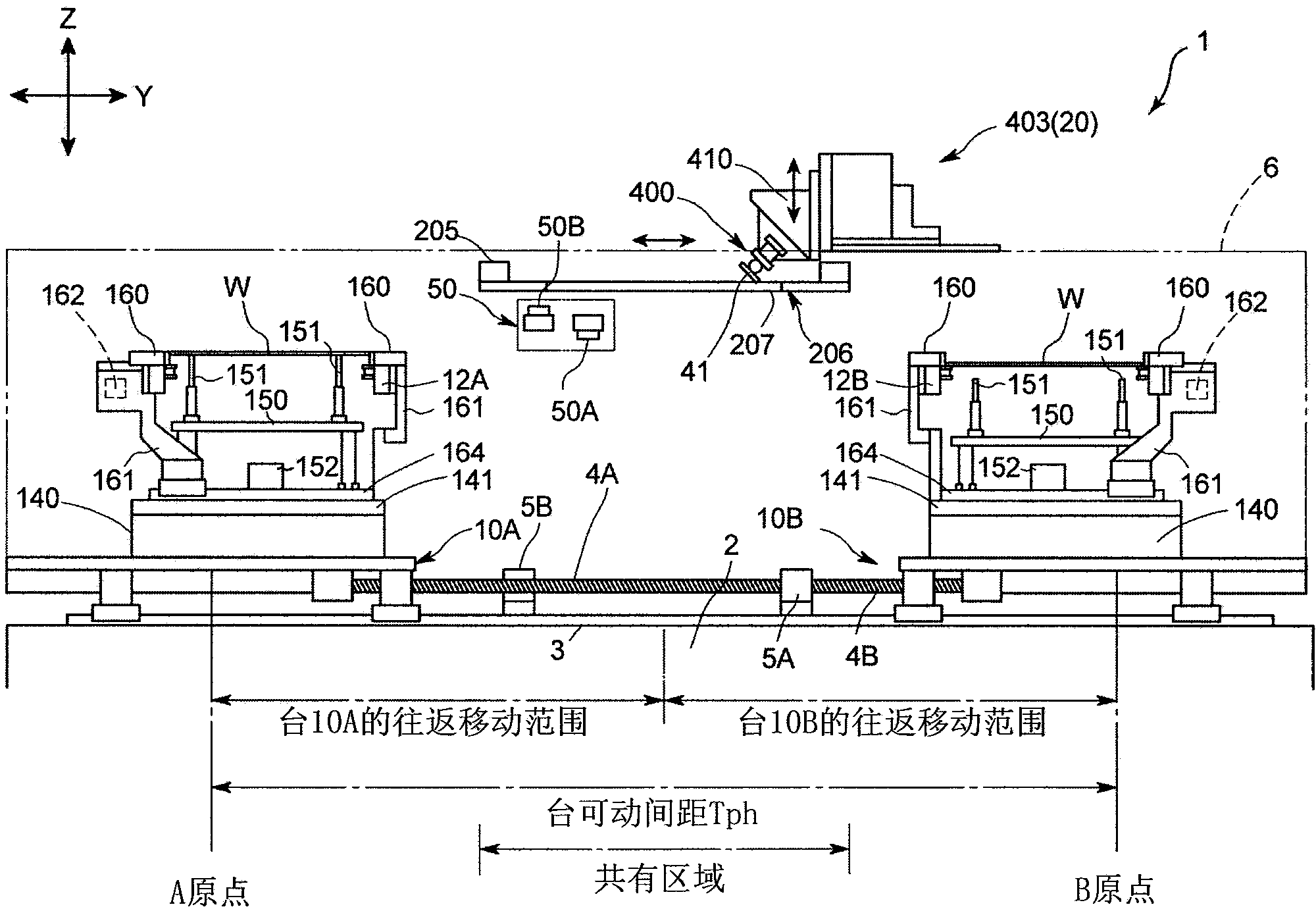
[0160] Therefore, in the third embodiment, as Figure 27 As shown, after performing the determination of the delay (step S105), calculate the time Tr (step S110) required for the substrate support table 10B that has moved into the action to enter the current printing position (step S110), and calculate the print execution unit 20 to the substrate support table. 10B moves the position Pr of Tr / 2 (step S111 ), and moves the substrate support table 10B and the print executing unit 20 to positions Pr, respectively.

[0161] If executed as Figure 27 In general processing, even if a d...


PUM


Abstract

Disclosed is a screen printing device that has low redundancy, is low cost, and is compact, while maintaining high production efficiency, and that is able to be adapted to a dual-transport component mounting device. The present invention is provided with: a pair of substrate holding tables (10A, 10B) that are provided in order to hold substrates (W) that are to be printed, and are disposed in parallel along the y-axis direction perpendicular to the direction of transport of the substrates (W); and a printing execution unit (20) that executes a printing step alternatingly to the substrates (W) supported at the pair of substrate supporting tables (10A, 10B). A printing position (SP) at which both substrate supporting tables (10A, 10B) perform alternating printing is altered within the range at which one of the substrate supporting tables (10A (10B)) and the other substrate supporting table (10B (10A)) face each other by means of the printing execution unit (20) being driven along the y-axis direction by means of the control by a control unit (60).

Description

technical field [0001] The present invention relates to a screen printing device, in particular to a screen printing device that screen-prints cream solder or conductive paste onto substrates such as printed wiring boards (Printed Wiring Board: PWB) as Pre-processing for mounting electronic components on this substrate. Background technique [0002] The screen printing device is installed in a printed circuit board (PCB) production line, and after performing screen printing with conductive paste or the like on the substrate conveyed from the upstream side, the substrate is sent to the downstream side for component mounting device. In order to improve production efficiency, for example, a screen printing apparatus disclosed in Patent Document 1 has been developed. In this screen printing apparatus, a pair of substrate support tables arranged side by side in a horizontal direction perpendicular to the conveying direction of the substrate are provided in the apparatus. And a ...

Claims


Application Information

Patent Timeline
Patent Type & Authority Applications(China)
IPC IPC(8): B41F15/26B41F15/08B41F15/36H05K3/12H05K3/34
CPCH05K3/1216H05K3/0085H05K13/0061H05K3/3484H05K13/0465B41F15/08B41F15/26B41F33/0036B41F33/0081B41F15/0881B41P2215/112B41P2215/114H05K3/3485
Inventor 三宅祥史藤本猛志
Owner YAMAHA MOTOR CO LTD
Why Eureka
Try Eureka