Automatic insulator scrubbing device

A technology of insulators and scrubbers, applied in the direction of insulators, chemical instruments and methods, cleaning methods and utensils, etc., can solve the problems of inconvenient operation, cleaning dead ends, and danger of climbing, and achieve the effect of simple operation and reduced labor

Inactive Publication Date: 2014-03-12
STATE GRID SHANDONG ELECTRIC POWER COMPANY WEIFANG POWER SUPPLY +1
7 Cites 59 Cited by

AI-Extracted Technical Summary

Problems solved by technology

The advantage of this cleaning method is that the workers scrub nearby, so the cleaning effect is the best. The disadvantage is that climbing poles are required for operation, so there are disadvantages such as the danger of climbing, the labor intensity of high-altitude operations, the inconvenience of operation, the need for the cooperation of auxiliary personnel, and low work efficiency. ...

Method used

Because at least three insulators are installed on an electric pole or a tower pole, therefore this insulator automatic scrubber can be installed on an insulator earlier and start work, then another cover of insulator is installed on the second insulator to automatically The scrubber starts to work, and after the insulator automatic scrubber on the first insulator is finished scrubbing, it is installed on the third insulator to continue working, and so on, which can effectively improve the scrubbing efficiency.
[0027] The main half-ring 4 and the secondary half-ring 5 inner wall are equipped with a brush 6 extending to the axis, that is, the inner wall of the ring is evenly distributed with a brush 6. When the ring rotates, the insulator inserted in the ring can be scrubbed. Gear teeth 9 are evenly distributed on the outer ring wall of the main half ring 4 and the auxiliary half ring 5, that is, gear teeth are evenly distributed on the outer ring wall of the circular ring, so that the ring forms an external gear ring. Scrubbing motor 7 is installed on the half-ring track, and the output shaft of scrubbing motor 7 is equipped with gears meshed with the outer gear ring, so that when the motor is energized, the outer gear ring can be driven by the gear to rotate, and the setting is realized. The automatic scrubbing of the insulator in the outer gear ring not only assists in scrubbing the insulator, but also saves time and effort. The insulator automatic scrubber realizes the 360-degree scrubbing of the outer circumference of the insulator through the rotation of the ring or the outer gear ring, so there is no dead angle for scrubbing, and the scrubbing effect is guaranteed.
[0030] In the present embodiment, the half-ring track 3 is a "C"-shaped half-ring groove in cross section, and the half-ring groove includes a half-ring cavity 10 and an annular mouth 11 communicated with the half-ring cavity 10. The main half-ring 4 and the auxiliary half-ring 5 are half-ring shuttles with a "T" shape in cross-section, and the half-ring shuttles include an inner sliding part 12 that is slidably fitted with the half-ring cavity 10 and an extension that extends from the ring mouth 11 13. The half-ring track 3 adopts a half-ring groove structure, and the main half-ring and the auxiliary half-ring adopt the structure of a half-ring shuttle. The semi-annular inner cavity wall of the ring groove is sliding fit. Balls 14 are evenly distributed on the wall of the half-ring cavity, which can reduce the sliding friction force between the inner sliding part 12 and any part of the half-ring cavity 10, that is, enhance the smoothness of the ring sliding in the half-ring track 3 . The extended portion 13 of the half-ring shuttle extends from the annular mouth 11 of the half-ring groove, and the half-ring shuttle is connected with external mechanisms through the extended portion, such as installing a brush, a docking device, and the like.
[0031] In this insulator automatic scrubber, the elevating mechanism includes a rack 15 affixed to the right cover 2, and the rack 15 is vertically arranged. The sliding sleeve on the tooth bar 15 is provided with a sliding sleeve 16, and the sliding sleeve 16 is fixedly connected with the half ring track 3. A lifting motor 17 is installed on the sliding sleeve, and the rotating shaft of the lifting motor 17 cooperates with the transmission of the rack 15 through a reducer, and also includes a controller 18 for controlling the positive and negative rotation of the lifting motor. The sliding sleeve 16 slides up and down with the vertically arranged rack 15, and the lifting motor 17 installed on the sliding sleeve is matched with the gear rack after passing through the reducer. Realize the function of driving the sliding sleeve to slide up and down along the rack, and the operation is very simple. And because the half-ring track 3 is fixedly located on the sliding sleeve, therefore the lifting control to the half-ring track and the ring has also been realized, and the brush 6 can be controlled to scrub up and down in the insulator axial direction. The speed reducer or deceleration device is a conventional design of mechanical transmission, and its structure and principle belong to the known technology and will not be described in detail here.
[0033] In this embodiment, the docking mechanism includes a sleeve 19 and a sleeve rod 20 fixed on the extension of the main half ring and the auxiliary half ring respectively, an...

Abstract

The invention discloses an automatic insulator scrubbing device. The automatic insulator scrubbing device comprises a left cover and a right cover, wherein the left cover and the right cover are in fixed butt joint on the periphery of an insulator through connecting mechanisms, clamping parts in clamping fit with the two end portions of the insulator are arranged at the two ends of the left cover and the two ends of the right cover, a semi-ring rail is arranged on the left cover or the right cover through a lifting mechanism, a main semi-ring and an auxiliary semi-ring are arranged on the semi-ring rail in a sliding mode and are capable of rotating around the axial line of the semi-ring rail, the main semi-ring and the auxiliary semi-ring are fixedly connected to form a circular ring through butt-joint mechanisms, hairbrushes corresponding to the outer wall of the insulator are arranged on the inner ring wall of the main semi-ring and the inner ring wall of the auxiliary semi-ring, a scrubbing motor is arranged on the lifting mechanism, a driving gear is arranged on an output shaft of the scrubbing motor, and gear teeth meshed with the gear are evenly distributed on the outer ring wall of the main semi-ring and the outer ring wall of the auxiliary semi-ring. Through the adoption of the structure, the automatic insulator scrubbing device is reasonable in structure, capable of assisting in cleaning the insulator, free of cleaning dead angles, good in cleaning effect, capable of saving time and labor in operation, low in cost and beneficial to improving scrubbing efficiency.

Application Domain

Cleaning using toolsInsulators

Technology Topic

EngineeringButt joint +1

Image

  • Automatic insulator scrubbing device
  • Automatic insulator scrubbing device

Examples

  • Experimental program(1)

Example Embodiment

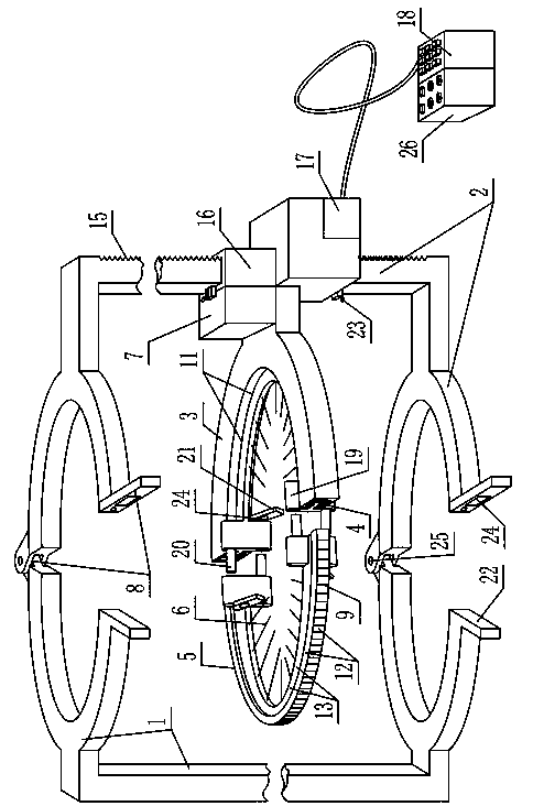
[0025] As shown in the figure, the insulator automatic scrubber includes a left cover 1 and a right cover 2 that are matched with the outer periphery of the insulator. In this embodiment, the left cover 1 and the right cover 2 adopt a bracket structure, and the plate surface can also be used in specific manufacturing. Structure or mesh structure.
[0026] The corresponding sides of the left cover 1 and the right cover 2 are fixedly connected together by the connecting mechanism 8. The two ends of the left cover 1 and the right cover 2 are provided with clamping parts that are matched with the two ends of the insulator. When the left cover 1 and the right cover 2 When connected together by the connecting mechanism, the clamping part is clamped on both ends of the insulator. The automatic insulator scrubber is fixedly clamped and installed on the insulator through the clamping part, which is very convenient to install. In this way, it is equivalent to cover the insulator with an outer cover formed by butting the left cover 1 and the right cover 2. The outer cover, namely the left cover and the right cover, constitute the main support of the insulator automatic scrubber. A half-ring track 3 is installed on the right cover 2 through a lifting mechanism, the half-ring track 3 is in a semi-circular ring shape, and the recess of the half-ring track is arranged corresponding to the outer wall of the insulator. The main function of the lifting mechanism is to drive the half-ring track 3 to lift, that is, to drive the half-ring track to move between the upper and lower parts of the outer periphery of the insulator. The half-ring track 3 is provided with a main half-ring 4 and a secondary half-ring 5 that can slide along the half-ring track. The main half-ring 4 and the secondary half-ring 5 are fixedly connected to form a complete ring through a docking mechanism, so that the main half The ring 4 and the sub-half ring 5 are assembled on the outer periphery of the insulator. For the convenience of description, the ring structure formed by the main half ring and the auxiliary half ring fixed by the docking mechanism is called the ring. In this way, the circular ring can slide along the semi-circular rail 3 under the support of the semi-circular rail 3 with the axis of the semi-circular rail 3 as the center line, that is, the circular ring can go around the semi-circular rail 3 axis. The wire or insulator rotates.
[0027] The inner ring walls of the main half ring 4 and the auxiliary half ring 5 are equipped with brushes 6 extending toward the axis line, that is, brushes 6 are uniformly distributed on the inner wall of the ring. When the ring rotates, the insulator inserted in the ring can be scrubbed. The outer ring walls of the main half ring 4 and the auxiliary half ring 5 are uniformly distributed with gear teeth 9, that is, the outer ring walls are uniformly distributed with gear teeth, so that the ring constitutes an outer gear ring. A scrubbing motor 7 is installed on the half-ring track, and the output shaft of the scrubbing motor 7 is equipped with a gear that meshes with the outer gear ring, so that when the motor is energized, the outer gear ring can be driven to rotate through the gear, and the setting is realized. The automatic scrubbing of the insulator in the outer gear ring can not only assist in scrubbing the insulator, but also save time and effort. The automatic scrubber for insulators realizes the 360-degree scrubbing of the outer circumference of the insulator through the rotation of the ring or the outer gear ring, so there is no dead corner during scrubbing and the scrubbing effect is ensured.
[0028] When using this insulator automatic scrubber, first fix the left cover 1 and the right cover 2 on both ends of the insulator through the connecting mechanism 8, and then connect the main half ring 4 and the secondary half ring 5 to the outside of the insulator through the docking mechanism, and finally start the scrubbing The motor 7 power supply and controls the lifting mechanism to lift, so that the outer circumference of the insulator can be scrubbed circumferentially (around the insulator) and axially (up and down). Therefore, workers only need to climb the pole to fix it without scrubbing operation, which greatly reduces labor and saves money. Save time and effort. After scrubbing, the main half ring and the secondary half ring are separated by unlocking the docking mechanism, and then the connecting mechanism is unlocked to remove the left cover and the right cover from the insulator. This completes the disassembly work and the operation is very simple.
[0029] Because there are at least three insulators installed on an electric pole or tower pole, you can install this insulator automatic scrubber on one insulator and start the work, and then install another set of insulator automatic scrubber on the second insulator. Start work, wait for the insulator automatic scrubber on the first insulator to finish scrubbing, and then install it on the third insulator to continue working, and so on, which can effectively improve scrubbing efficiency.
[0030] In this embodiment, the half-ring track 3 is a half-ring groove with a “C”-shaped cross-section. The half-ring groove includes a half-ring cavity 10 and an annular opening 11 communicating with the half-ring cavity 10. The main half-ring 4 and the secondary half-ring 5 are half-ring shuttles with a "T"-shaped cross-section. The half-ring shuttle includes an inner sliding portion 12 slidingly fitted with the half-ring cavity 10 and an extension portion extending from the annular opening 11 13. The half-ring track 3 adopts a half-ring groove structure, and the main half-ring and the secondary half-ring adopt the structure of a half-ring shuttle. The inner sliding part 12 of the half-ring shuttle is arranged in the half-ring cavity 10 of the half-ring groove, and the two are along the half-ring groove. The semi-annular cavity wall of the ring groove is in sliding fit. Balls 14 are evenly distributed on the wall of the half-ring cavity, which can reduce the sliding friction between the inner sliding portion 12 and any part of the half-ring cavity 10, that is, to enhance the smoothness of the circular ring sliding in the half-ring track 3. The extension portion 13 of the half-loop shuttle extends from the annular opening 11 of the half-ring groove, and the half-loop shuttle is connected to external mechanisms through the extension portion, such as installing a brush, a docking device, and the like.
[0031] In the automatic scrubber for insulators, the lifting mechanism includes a rack 15 fixedly connected to the right cover 2, and the rack 15 is vertically arranged. A sliding sleeve 16 is fitted on the rack 15 to slide, and the sliding sleeve 16 is fixedly connected to the half-ring rail 3. A lifting motor 17 is installed on the sliding sleeve. The rotating shaft of the lifting motor 17 is driven to cooperate with the rack 15 through a reducer, and also includes a controller 18 that controls the forward and reverse rotation of the lifting motor. The sliding sleeve 16 and the vertically arranged rack 15 slide up and down. The lifting motor 17 installed on the sliding sleeve is matched with the rack transmission after passing through the reducer. Therefore, the forward and reverse rotation of the lifting motor 17 can be controlled by the operation controller 18 The function of driving the sliding sleeve to slide up and down along the rack is realized, and the operation is very simple. And because the half-ring track 3 is fixed on the sliding sleeve, the lifting control of the half-ring track and the ring is realized, and the brush 6 can be controlled to scrub up and down in the axial direction of the insulator. The reducer or reduction gear is a conventional design of mechanical transmission, and its structure and principle belong to well-known technology, and will not be described in detail here.
[0032] A position sensor 23 corresponding to the upper and lower limit positions is installed on the sliding sleeve 16, and the position sensor 23 is electrically connected with the input terminal of the controller 18. The position sensor 23 can detect the upper limit and lower limit of the sliding sleeve 16 on the rack, and transmit the position detection signal to the controller 18, so that the controller can determine that the sliding sleeve has reached the upper limit or the lower limit, thereby The lifting motor 17 is controlled to reverse. In actual production, the position sensor can use a travel switch, the upper limit and the lower limit can be replaced by the part between the clamping part of the left and right covers and the rack, and the controller can adopt the common DC motor forward and reverse on the market. The structure and working principle of the controller belong to the well-known technology and will not be described in detail here. In actual use, the controller can be carried by workers for high-altitude operation after climbing, or it can be placed on the ground together with the motor power supply 26 and operated by ground workers, which can be selected according to actual needs, which is more convenient to use.
[0033] In this embodiment, the docking mechanism includes a sleeve 19 and a sleeve rod 20 respectively fixed on the outer extensions of the main half ring and the secondary half ring, and the sleeve 19 and the sleeve rod 20 are inserted and fitted. The end of the sleeve 19 farther from the sleeve rod 20 is hinged with a locking plate 21 through a hinge axis parallel to the sleeve rod. The locking plate 21 is fixedly provided with a magnetic block 24 for attracting and closing the end of the sleeve rod 20. Because the sleeve 19 and the sleeve rod 20 that are inserted and fitted are respectively arranged on the extension portion 13 of the corresponding ends of the main half ring 4 and the secondary half ring 5, the sleeve 19 and the sleeve rod 20 will not be in contact with each other when the ring rotates. The collision of the half-ring track or other components ensures the reliability of rotation. The sleeve 19 and the sleeve rod 20 are inserted and fitted together, that is, the sleeves and the sleeve rods are arranged horizontally and parallel, so that after the horizontal insertion, the locking or stability of the sleeve rod in the radial direction can be ensured. That is, the two cannot move up and down, nor can they move left and right, which ensures that the main half ring 4 and the secondary half ring 5 are in the same plane. The sleeve 19 and the sleeve rod 20 are locked or fixed in the axial direction by a locking plate 21 hinged on the end of the sleeve and a magnetic block 24 mounted on the locking plate 21. Because the hinge shaft between the locking plate 21 and the sleeve 19 is parallel to the sleeve rod, the locking plate can swing freely in the end surface of the sleeve around the hinge shaft. When it is necessary to connect the main half ring and the secondary half ring into a circular ring, insert the sleeve rod 20 into the sleeve 19, swing the locking plate 21, and make the magnetic block 24 on the locking plate 21 align with the end surface of the sleeve rod 20. When the end surface of the sleeve rod is aligned with the magnetic block, the magnetic block attracts the sleeve rod with the strongest suction force, which can reliably lock the sleeve rod axially. This state is called the locked state. When it is necessary to separate the main half ring and the auxiliary half ring, push the locking plate to rotate around the hinge axis. At this time, since the magnetic block exerts a small radial force on the end face of the sleeve rod, the magnetic block and the sleeve rod can be easily connected The end faces are staggered. At this time, the overlapping area of ​​the two is reduced, the distance is increased, and the magnetic force is weakened. Therefore, the magnetic block and the end face of the sleeve can be easily separated, so that the separation of the sleeve and the sleeve is realized. This state is called unlocking status. Setting the number of sleeves and sleeve rods to two or more sets can enhance the docking reliability of the main half ring and the auxiliary half ring, and make the ring rotate more smoothly.
[0034] In this embodiment, the connecting mechanism 8 includes a hinge shaft 25 for hingedly connecting the left cover 1 and the right cover 2 to the corresponding sides, and the hinge shaft 25 is arranged vertically. Because most of the insulators are arranged vertically, the left cover and the right cover are hinged together by the vertically arranged hinge shaft 25, which meets the requirements of the construction site and is more convenient and faster in installation. An iron block is fixed on the other side of the left cover 1, and a locking plate 21 is hinged on the other side of the right cover 2 through a hinge shaft in the same direction as the butting direction. The locking plate 21 is provided with a magnetic block 24 corresponding to the iron block. . In this connection mechanism, an iron block and a magnetic block installed through a hinged locking plate are respectively arranged on the other side of the left cover and the right cover, and the role of the sleeve rod and the magnetic block installed through the hinged locking plate in the docking mechanism Similarly, they are all to enhance the magnetic attraction or locking force of the two sides of the docking, that is, the iron block and the magnetic block in the docking direction, and weaken the magnetic attraction between the two in the direction perpendicular to the docking direction, so as to achieve simple operation during docking, and after docking It is tight and reliable, and it is easy to save effort when separating.

PUM

no PUM

Description & Claims & Application Information

We can also present the details of the Description, Claims and Application information to help users get a comprehensive understanding of the technical details of the patent, such as background art, summary of invention, brief description of drawings, description of embodiments, and other original content. On the other hand, users can also determine the specific scope of protection of the technology through the list of claims; as well as understand the changes in the life cycle of the technology with the presentation of the patent timeline. Login to view more.

Similar technology patents

Cereal drying device

Owner:安徽雨坛生态农业科技发展有限公司

Medical image examination equipment for cardiovascular medicine department

ActiveCN109998579Areduce laborGuaranteed shooting quality
Owner:FUWAI HOSPITAL CHINESE ACADEMY OF MEDICAL SCI

Classification and recommendation of technical efficacy words

  • reduce labor
  • easy to operate

Intelligent trolley for saving and taking books in library

InactiveCN104354155Areduce laborwork fast
Owner:SHAANXI UNIV OF SCI & TECH

Flat-plate antenna and method for manufacturing the same

InactiveUS6917333B2reduce laborthin shape
Owner:HITACHI METALS LTD

Molding press apparatus

InactiveUS6106275Areduce laborimprove quality
Owner:AEROJET ROCKETDYNE HLDG INC

Double-faced carving machine for wooden door leaf

ActiveCN104191886Aeasy to operatereduce labor
Owner:NANTONG YUETONG CNC EQUIP CO LTD

Lancet device

InactiveUS7303573B2inexpensively mass-producedeasy to operate
Owner:ABBOTT DIABETES CARE INC

Rapid and non-invasive optical detection of internal bleeding

InactiveUS20050065436A1easy to operaterapid and accurate result
Owner:HO WINSTON ZONH +2
Why Eureka
Try Eureka