
Pipe cutting deice

A cutting device and pipe material technology, applied in the direction of sawing machine, metal sawing equipment, metal processing equipment, etc., can solve the problems of time-consuming and power consumption, and achieve the effect of energy saving, non-rough section and fast cutting speed

Inactive Publication Date: 2014-03-12
NINGBO KANGRUN MACHINERY TECH
View PDF6 Cites 2 Cited by
  • Summary
  • Abstract
  • Description
  • Claims
  • Application Information

AI Technical Summary

Problems solved by technology

[0003] The purpose of the present invention is to solve the time-consuming and power-consuming problems of pipe cutting devices in the prior art, and to provide a pipe cutting device with low energy consumption and low time consumption to solve the above problems

Method used


Image

  • Pipe cutting deice
  • Pipe cutting deice

Examples


Embodiment Construction

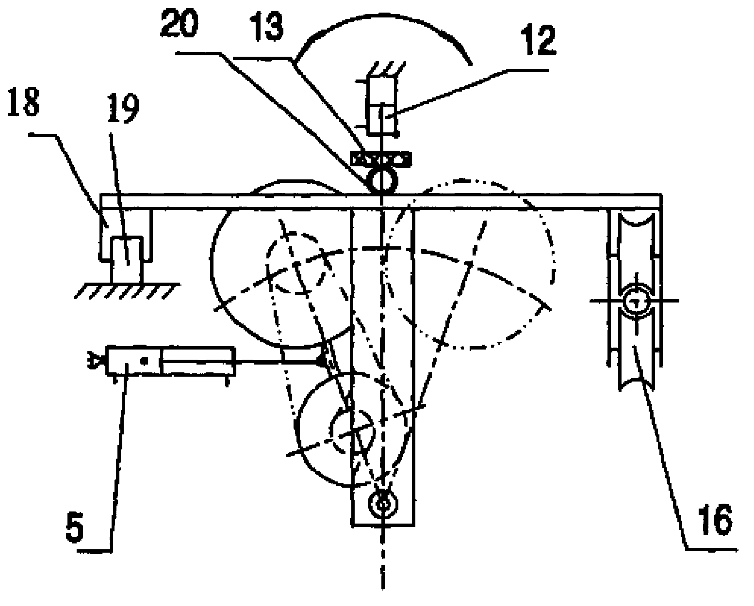
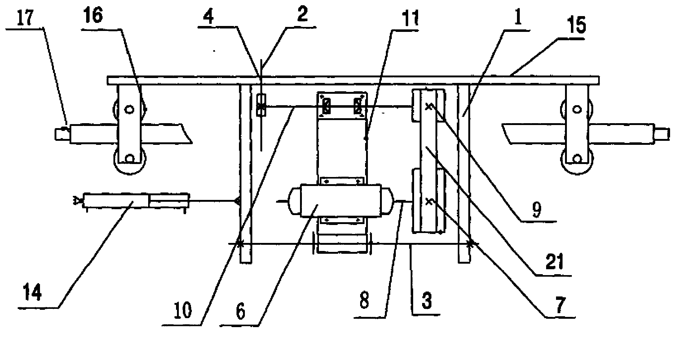
[0013] see figure 1 with figure 2 , a pipe cutting device, comprising: a frame 1 and a cutting assembly, the frame 1 includes a working platform and a rotating shaft 3, and the cutting assembly is installed on the rotating shaft 3 on the frame 1 consistent with the running direction of the pipe 20, the The rotating shaft 3 is fixedly connected with a swinging device, so the rotating shaft 3 is the swinging shaft of the cutting assembly, and the working platform is provided with a notch 4 that accommodates the swinging of the cutting assembly, wherein the cutting assembly includes a saw blade 2, a belt drive wheel and Drive motor 6, and saw blade 2 is higher than working platform, and the driving pulley 7 of described belt transmission wheel is connected with motor shaft 8, and the driven wheel of belt pulley is connected with saw blade 2 through saw blade shaft 10.

[0014] As a preferred solution, the oscillating device is a cutting cylinder 5 .

[0015] As a preferred sol...


PUM


Abstract

The invention discloses a pipe cutting device which comprises a rack and a cutting assembly. The pipe cutting device is characterized in that the rack a working platform and a rotary shaft. The cutting assembly is installed on the rotary shaft of the rack, the rotary shaft is fixedly connected with a swinging device, a notch is formed in the working platform and used for containing the cutting assembly to swing, and the cutting assembly comprises a saw blade, a belt pulley and a drive motor. A drive wheel of the belt pulley is connected with a motor shaft, and a driven wheel of the belt pulley is connected with the saw blade through a saw blade shaft. The pipe cutting device has the advantages of being high in cutting speed, saving energy and being not rough in cross section.

Description

technical field [0001] The invention relates to a pipe material cutting device, which belongs to the technical field of cutting equipment. Background technique [0002] Existing pipe cutting machines generally use the cutting saw blade to be directly connected to the cutting cylinder and move up and down to cut the pipe. Due to the up and down reciprocating method of cutting, the internal and external forces of the cut pipe are uneven, resulting in rough cross-section and unevenness. , and because the pipe can only be cut once up and down, the motor is directly connected to the cutting saw blade, and when the saw blade returns, it will take one more return time, which reduces work efficiency, increases cost, high energy consumption and long time. Contents of the invention [0003] The purpose of the present invention is to solve the time-consuming and power-consuming problems of the pipe cutting device in the prior art, and provide a pipe cutting device with low energy con...

Claims


Application Information

Patent Timeline
IPC IPC(8): B23D45/12
Inventor 徐新
Owner NINGBO KANGRUN MACHINERY TECH
Learn More