Flexible thin plate positioning fixture based on T-type groove

A positioning fixture and flexible technology, applied in manufacturing tools, auxiliary devices, auxiliary welding equipment, etc., can solve the problems of difficulty in establishing an assembly deviation analysis model, and achieve the effect of simple structure and convenient use.

Inactive Publication Date: 2014-03-12
SHANGHAI UNIV OF ENG SCI
View PDF6 Cites 22 Cited by
  • Summary
  • Abstract
  • Description
  • Claims
  • Application Information

AI Technical Summary

Problems solved by technology

These factors make it difficult to establish an assembly deviation analysis model, so it is ne

Method used


Image

  • Flexible thin plate positioning fixture based on T-type groove
  • Flexible thin plate positioning fixture based on T-type groove
  • Flexible thin plate positioning fixture based on T-type groove

Examples


Embodiment 1

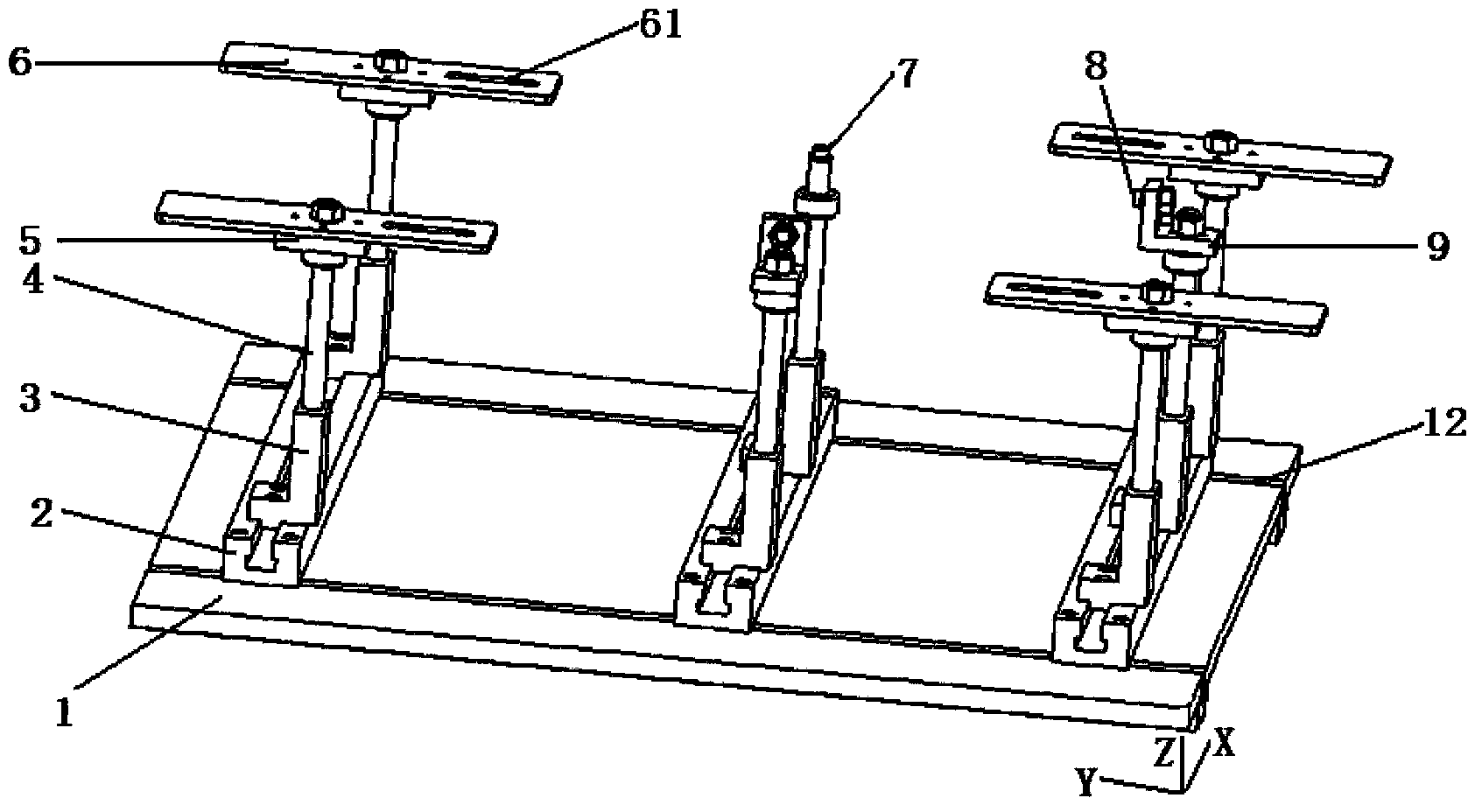
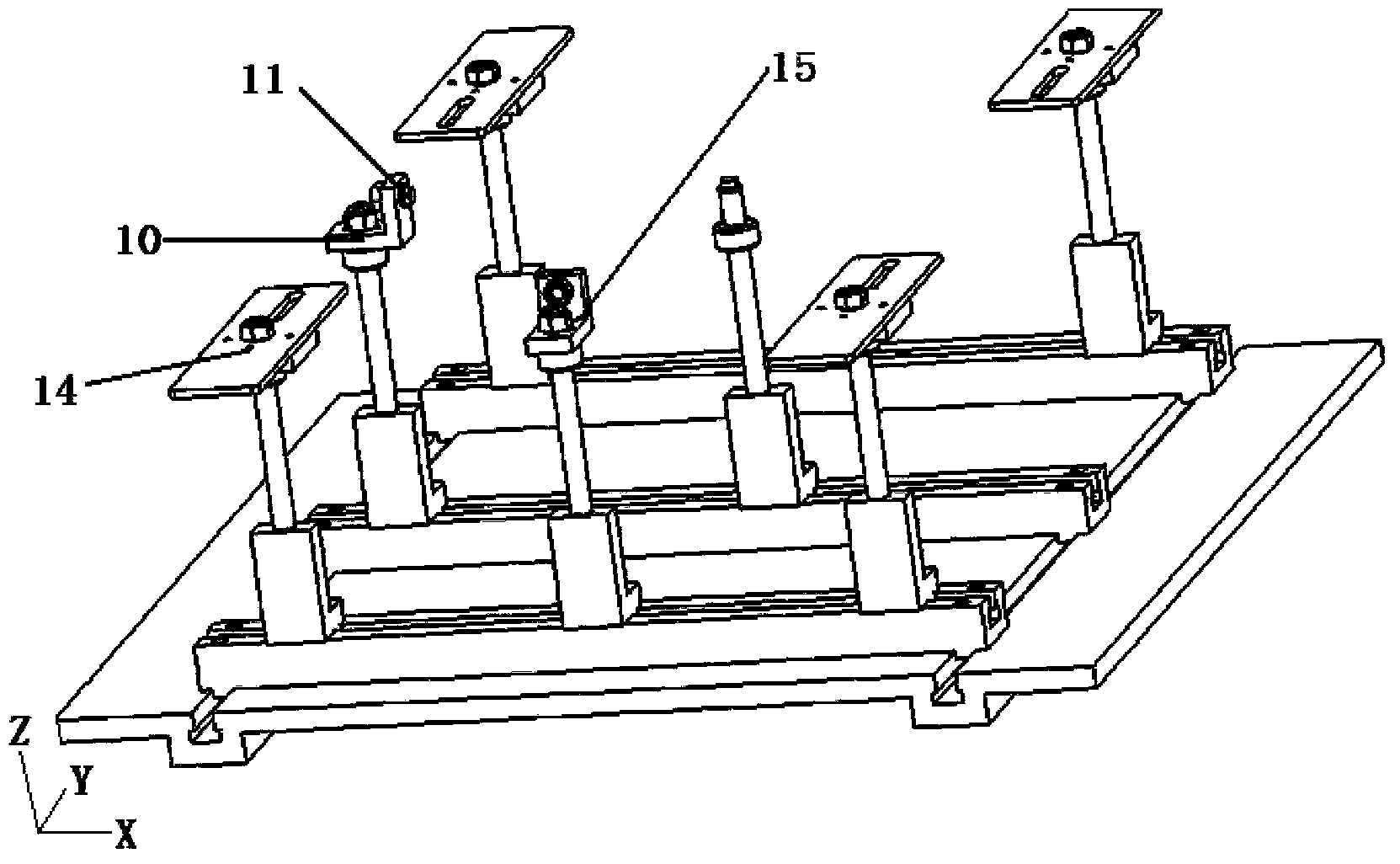
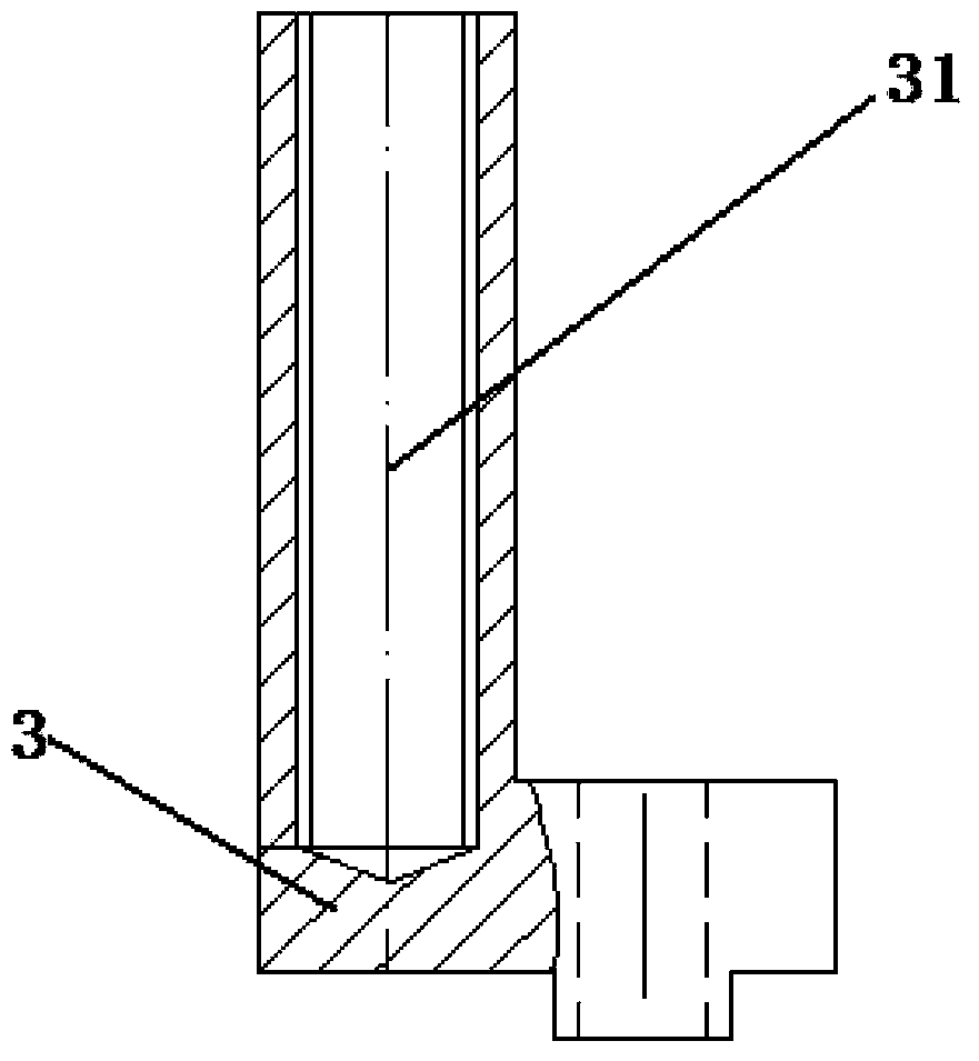
[0031] A flexible thin plate positioning fixture based on T-slot, the structure is as follows figure 1 and figure 2 As shown, the positioning fixture includes a fixture base plate 1, a T-slot slider 2, a support slider 3, a stud bolt 4, and positioning pins (including X-directional positioning pins 11, Y-directional positioning pins 8 or Z-directional positioning pins 7) , a positioning plate 5 and a chuck bracket 6, multiple T-slot sliders 2 are provided, which are slidably connected to the fixture bottom plate 1, and each T-slot slider 2 is slidably connected to 2 to 3 support sliders 3, double The lower end of the head bolt 4 is connected to the support slider 3, and the upper end of the stud bolt 4 is connected to the positioning pin (X-direction positioning pin 11, Y-direction positioning pin 8 or Z-direction positioning pin 7) or the chuck bracket through the positioning plate 5 6. Adjust the height of the positioning pin (X-direction positioning pin 11, Y-direction po...

Embodiment 2

[0043] Such as figure 1 and figure 2 As shown, the positioning fixture based on the T-slot flexible thin plate includes a fixture base plate 1, a T-slot slider 2, a support slider 3, a stud bolt 4, a positioning plate 5, a chuck bracket 6, and a Z-direction positioning pin 7. Y-direction positioning pin 8, Y-direction positioning pin bracket 9, X-direction positioning pin bracket 10, X-direction positioning pin 11.

[0044] There are three T-shaped groove sliders 2, which are evenly distributed on the fixture base plate 1, and each T-shaped groove slider 2 is fixed on the fixture base plate 1 by bolts and nuts so that it cannot move. Set seven support sliders 3 to be installed on the T-slot slider 2, and adjust their positions according to requirements, and then use T-slot bolts and nuts to fix the support slider 3. Install seven stud bolts 4 on the support slider 3, and adjust the thread fit position according to the height requirement. Install the positioning plate 5 and...


PUM

PropertyMeasurementUnit
Lengthaaaaaaaaaa
Heightaaaaaaaaaa

Abstract

The invention relates to a flexible thin plate positioning fixture based on a T-type groove. The positioning fixture comprises a fixture bottom plate, a plurality of T-type groove sliding blocks, supporting sliding blocks, double-head bolts, positioning pins, positioning plates and clamp head supports. The T-type groove sliding blocks are slidably connected to the fixture bottom plate, and each T-type groove sliding block is slidably connected with two or three supporting sliding blocks. The lower ends of the double-head bolts are connected to the supporting sliding blocks, and the upper ends of the double-head bolts are connected with the positioning pins or are connected with the clamp head supports through the positioning plates. The heights of the positioning pins and the heights of the clamp head supports are adjusted through the double-head bolts. The clamp head supports are rotably connected with the positioning plates. The positioning pins are rotably connected with the double-head bolts. Compared with the prior art, different numbers of positioning plates can be selected to achieve the strategy switching from 3-2-1 positioning to 6-2-1 positioning; meanwhile, because each assembly can be disassembled and replaced, flexible changes of positioning strategies can be achieved.

Description

technical field [0001] The invention relates to a flexible thin plate assembly fixture, in particular to a T-shaped slot-based flexible thin plate positioning fixture capable of adjusting three-dimensional positioning positions and positioning strategies. Background technique [0002] Flexible thin plate parts are widely used in automobile bodies, aircraft fuselage wings and other products. Since thin plate parts are easy to deform during welding, a new positioning principle "N-2-1" positioning strategy is required. This positioning strategy is the same as The six-point positioning principle of rigid body parts (ie 3-2-1) is more suitable for flexible thin plate parts, which can reduce the deformation of parts in the direction of the main plane. Generally speaking, N is greater than 3, usually 4 to 6. If there are too few anchor points on the main plane and N is less than or equal to 3, the deformation will be large. If N is greater than 6, there will be too many positionin...

Claims


Application Information

Patent Timeline
IPC IPC(8): B23K37/04
CPCB23K37/0408
Inventor 邢彦锋王岩松卢鑫陈娜雷杰张涛
Owner SHANGHAI UNIV OF ENG SCI
Why Eureka
Try Eureka