Supercharge Your Innovation With Domain-Expert AI Agents!

Assembling machine

An assembly machine and assembly table technology, applied in assembly machines, metal processing equipment, manufacturing tools, etc., can solve the problems of high cost, low degree of automation, difficulty in achieving angle and position accuracy, and improve stability and reliability. , the effect of improving assembly efficiency

Inactive Publication Date: 2014-03-12
SUZHOU YIMEIDE TECH CO LTD
View PDF6 Cites 11 Cited by
  • Summary
  • Abstract
  • Description
  • Claims
  • Application Information

AI Technical Summary

Problems solved by technology

[0002] In the electronics industry and the automobile industry, it is often necessary to assemble parts and components. The traditional manual assembly method is far from meeting the industry's requirements for assembly accuracy and assembly efficiency.
After the assembly is completed, the manual operation of the three-coordinate measuring machine is mainly used to detect the assembly results, which is slow and expensive
[0003] refer to Figure 1 ~ Figure 2 As shown, in the production process of an existing product, it is necessary to assemble the lens (code name: Rcam, referred to as the workpiece A to be assembled here) and the middle plate (code name: Housing, referred to as the workpiece B to be assembled here) to On the product body (referred to as the workpiece C to be assembled here), because there is no reliable spatial position to provide a reference around each workpiece, it is difficult to achieve the angle required by the process whether it is manually or with the help of auxiliary fixtures. and position accuracy, the yield rate cannot be guaranteed, laborious and laborious, and the degree of automation is low

Method used


Image

  • Assembling machine
  • Assembling machine
  • Assembling machine

Examples


Embodiment Construction

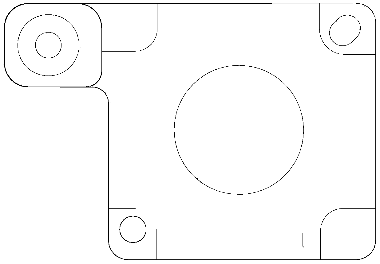
[0017] Figure 4 A specific embodiment of this assembly machine of the present invention is shown, which includes a frame (not shown in the figure), an assembly platform 1 located on the top of the frame, a robot arm 2, and a robot arm controller (not shown in the figure). drawn), where the robotic arm is mainly used to grab the workpiece A (Rcam) and the workpiece B (Housing) to be assembled, and the robotic arm controller is mainly used to control the movement of the robotic arm.

[0018] A push-pull movable frame (not shown in the figure) is installed on the assembly table 1, and when a pushing or pulling force is applied to the movable frame, it can move forward and backward. The movable frame is provided with two material seats 3 for fixing the workpiece C to be assembled (that is, the product body mentioned in the background technology), and the two material seats 3 are distributed one after the other on the movable frame. During use, the workpiece C to be assembled can...


PUM


Abstract

The invention discloses an assembling machine, which comprises a rack, an assembly station, a mechanical arm and a mechanical arm controller, wherein the assembly station is arranged on the top of the rack; the mechanical arm is used for grabbing a workpiece A to be assembled and a workpiece B to be assembled; the mechanical arm controller is used for controlling the mechanical arm to act; the assembly station is provided with a push-pull moving frame capable of being pushed and pulled to move back and forth, and a positioning mechanism used for fixing the front and back position of the moving frame; the moving frame is provided with a material seat used for fixing a workpiece C to be assembled; the assembly station is also provided with a first CCD (charge coupled device) industrial camera and five second CCD industrial cameras, wherein the first CCD industrial camera is positioned below the mechanical arm; the five second CCD industrial cameras are positioned above the push-pull moving frame; and the first CCD industrial camera and the second CCD industrial cameras are all electrically connected with the mechanical arm controller. The assembling machine has the advantages of high assembling precision and high assembling speed.

Description

technical field [0001] The present invention relates to an assembly machine. Background technique [0002] In the electronics industry and the automobile industry, it is often necessary to assemble parts and components. The traditional manual assembly method is far from meeting the industry's requirements for assembly accuracy and assembly efficiency. After the assembly is completed, the manual operation of the three-coordinate measuring machine is mainly used to detect the assembly results, which is slow and expensive. [0003] refer to Figure 1 ~ Figure 2 As shown, in the production process of an existing product, it is necessary to assemble the lens (code name: Rcam, referred to as the workpiece A to be assembled here) and the middle plate (code name: Housing, referred to as the workpiece B to be assembled here) to On the product body (referred to as the workpiece C to be assembled here), because there is no reliable spatial position to provide a reference around each w...

Claims


Application Information

Patent Timeline
IPC IPC(8): B23P21/00
CPCB23P21/002
Inventor 靳登科王妹婷崔惠峰
Owner SUZHOU YIMEIDE TECH CO LTD
Features
  • R&D
  • Intellectual Property
  • Life Sciences
  • Materials
  • Tech Scout
  • Unparalleled Data Quality
  • Higher Quality Content
  • 60% Fewer Hallucinations
Learn More