Improved glass polishing machine

A polishing machine, an improved technology, applied in surface polishing machine tools, grinding/polishing equipment, grinding/polishing safety devices, etc., can solve the problems of the inability to reach the polishing liquid quickly, the stability is not enough, and the production is inconvenient.

Inactive Publication Date: 2014-03-12
ZHUZHOU JOYSING TECH DEV
View PDF1 Cites 12 Cited by
  • Summary
  • Abstract
  • Description
  • Claims
  • Application Information

AI Technical Summary

Problems solved by technology

[0005] (2) The degree of automation needs to be improved: if manual switching of the liquid injection hose is used, it is inevitable that the operator will forget to switch the liquid injection hose due to negligence, resulting in the dilution of the polishing liquid in the polishing liquid recovery bucket after being mixed with clean water, which will bring problems to the production. Great inconvenience, affecting the quality of subsequent products;
[0006] (3) Insufficient stability: the upper fixed plate changes direction frequently during the horizontal back and forth movement than in high-speed operation, and the impact force on the upper fixed plate and the slide rail for its installation is large, which affects the stability of the glass polishing machine;
[0007] (4) The polishing liquid cannot quickly reach all parts of the workpiece surface: the polishing liquid is directly input to the liquid injection hole of the upper fixed plate through the liquid injection hose. Due to the limited number of liquid injection hoses, only a small amount of liquid injection can be set The hole is used to input the polishing liquid to the workpiece, and then, the polishing liquid cannot reach all parts of the workpiece quickly, which affects the polishing quality of the workpiece

Method used


Image

  • Improved glass polishing machine
  • Improved glass polishing machine
  • Improved glass polishing machine

Examples


Embodiment Construction

[0095] The technical scheme of the present invention will be further described below in conjunction with the accompanying drawings and through specific embodiments:

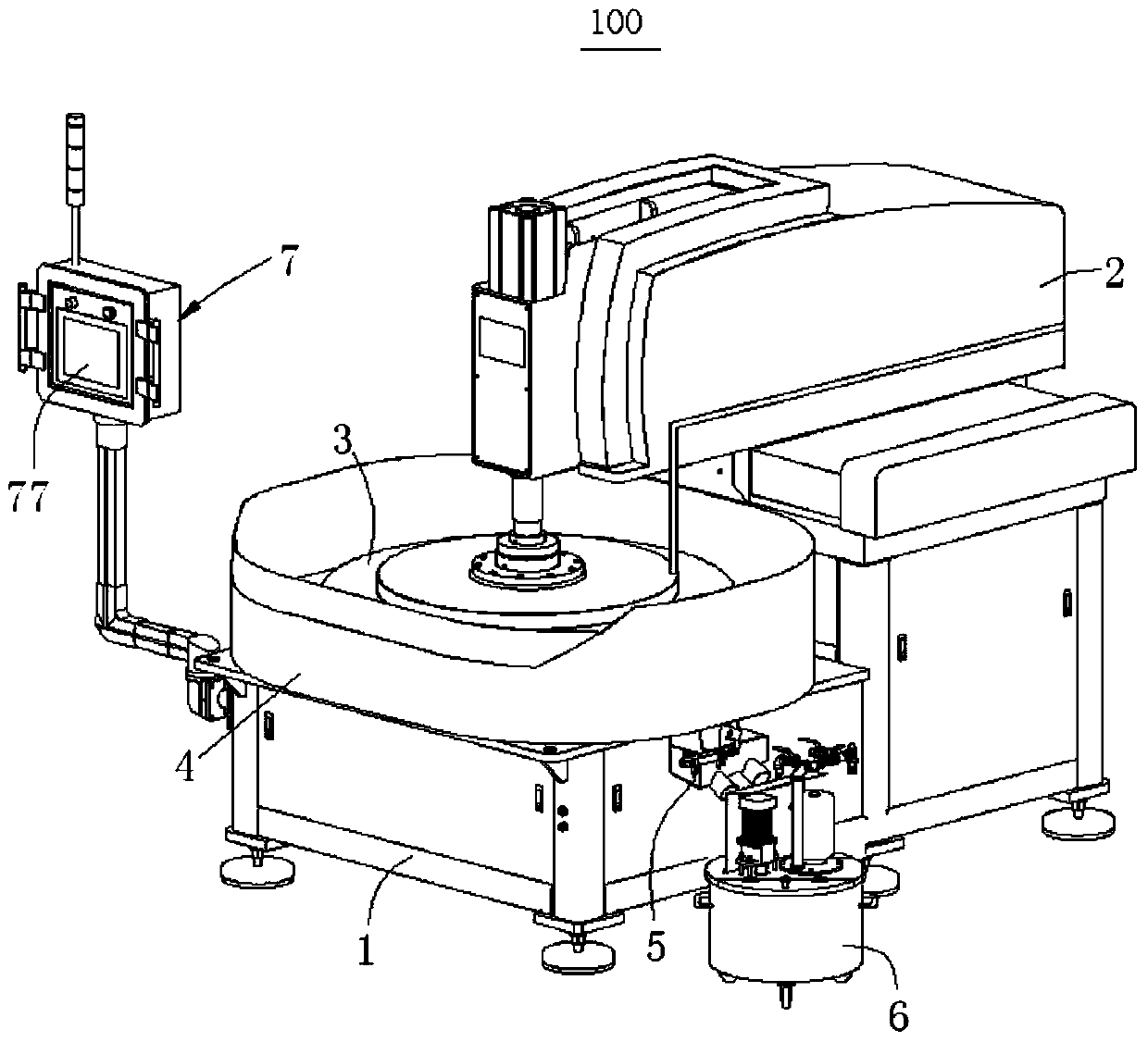
[0096] see figure 1 , the present invention provides an improved glass polishing machine 100, which includes a base 1, an upper fixed plate module 2, a lower fixed plate module 3, a liquid receiving plate 4, an automatic liquid-water separation device 5, a polishing liquid recovery bucket 6 and Programmed control system7.

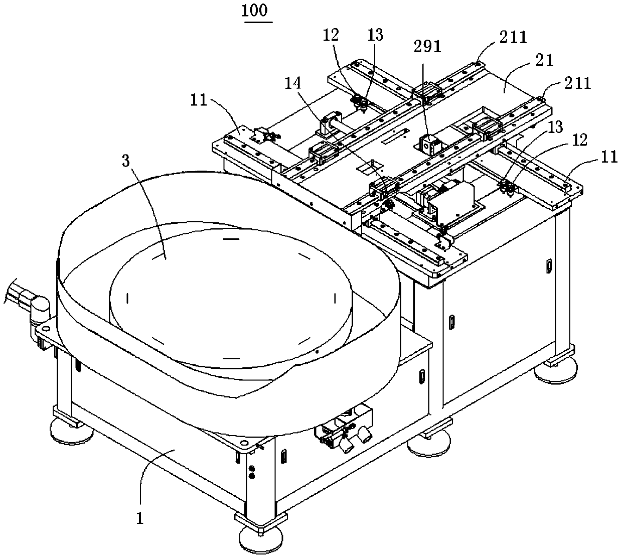
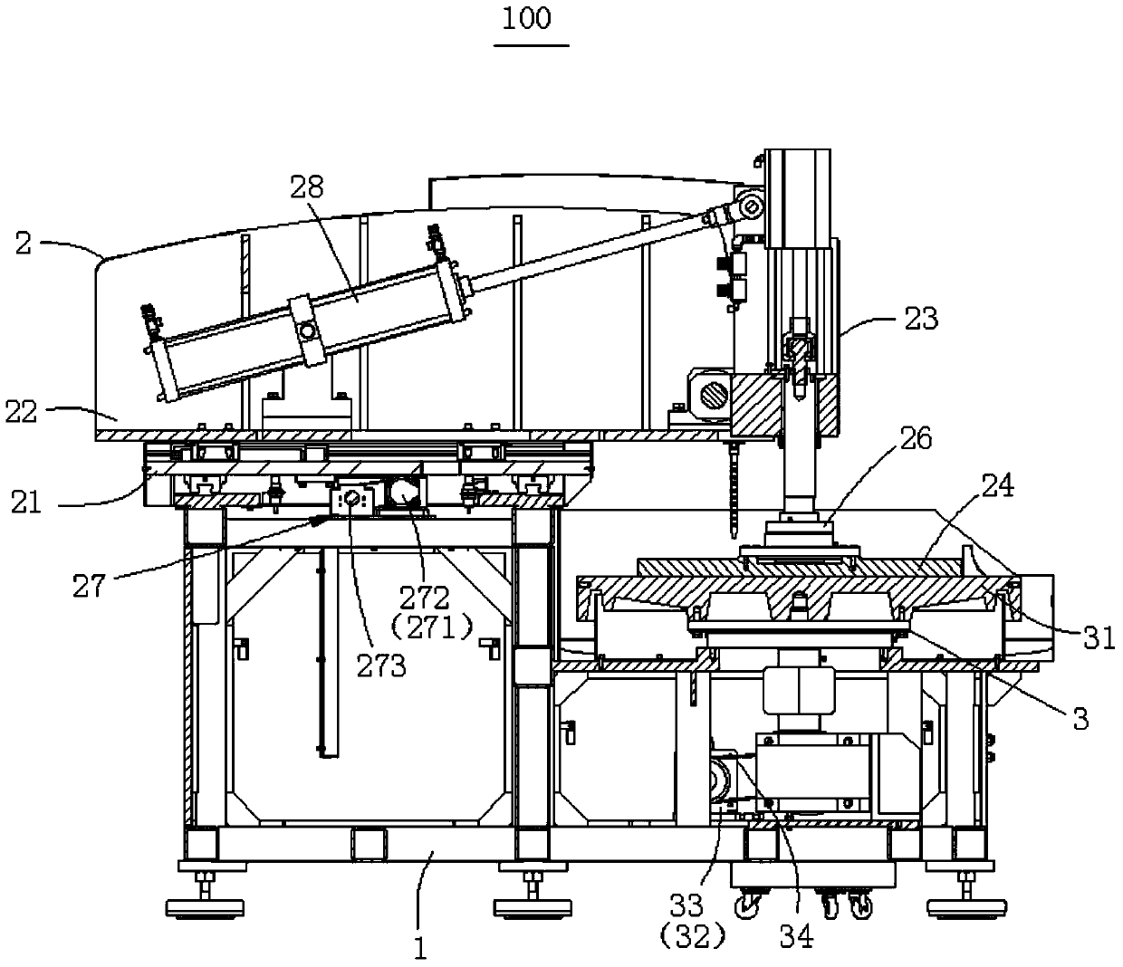
[0097] see Figure 1 to Figure 3 The base 1 is provided with two transverse slide rails 11 for sliding installation of the upper fixed plate module 2, and a plurality of travel switches (12, 13, 14 and 15), specifically, in this embodiment, the travel switch includes two limit position stop switches 12 arranged near the two ends of the transverse slide rail 11, and two deceleration switches located inside the limit position switch 13, and a middle position stop switch 14 corresponding to th...


PUM


Abstract

The invention discloses an improved glass polishing machine. The improved glass polishing machine comprises a base, an upper fixed disk module, a lower fixed disk module, a liquid receiving disk, an automatic liquid and water separation device, a polishing liquid recovery barrel and a programmed control system. The power of the improved glass polishing machine is only 60% of the power of a current conventional glass polishing machine, however, the improved glass polishing machine can complete the same polishing work. The improved glass polishing machine is provided with the automatic liquid and water separation device, so that the degree of automation is further improved, and therefore the problem that clear water affects the quality of polishing liquid is avoided. A plurality of travel switches are arranged on crosswise slide rails of the improved glass polishing machine so as to control the upper fixed disk module to move crosswise, so that the situation that the upper fixed disk module swerves while running at a high speed is avoided, therefore, impact to the upper fixed disk module and the crosswise slide rails allowing the upper fixed disk module to be installed is lower and the stability of running is guaranteed. An annular flow diversion channel is formed between a liquid injection hose and an upper fixed disk, a plurality of liquid injection holes are formed in the positions, below the annular flow diversion channel, of the upper fixed disk, so that the polishing liquid can enter all parts of the surface of a workpiece quickly and the polishing quality is guaranteed accordingly.

Description

technical field [0001] The invention relates to a glass polishing machine, in particular to an improved glass polishing machine. Background technique [0002] The glass polishing machine commonly used in the industry, such as a bottom-mounted single-sided polishing machine disclosed in the Chinese mainland invention patent, the publication number of this patent is CN102303278, and the publication time is January 4, 2012. The bottom-mounted single-sided polishing machine The basic working process is: the main motor of the lower fixed plate drives the lower fixed plate to rotate through the reducer, the main shaft of the lower chassis, the coupling, the lower fixed plate bearing, the inner sleeve of the bearing, and the lower fixed plate backing plate. End bearings, branch line guide rails, and the upper fixed plate base of the swing box drive the entire swing part to swing left and right. The plate rotates, and the polishing liquid in the polishing liquid barrel is injected ...

Claims


Application Information

Patent Timeline
IPC IPC(8): B24B29/02B24B57/00B24B57/02B24B55/00
CPCB24B29/02B24B51/00B24B57/00B24B57/02
Inventor 黄湘伟徐新生
Owner ZHUZHOU JOYSING TECH DEV
Why Eureka
Try Eureka