Log automatic stacking device
What is Al technical title?
Al technical title is built by PatSnap Al team. It summarizes the technical point description of the patent document.
A log, moving motor technology, applied in transportation and packaging, conveyor objects, roller tables, etc., can solve the problems of high labor intensity of operators, inability to meet modern production, slow stacking speed, etc., to achieve low labor intensity and structure. Novel, fast stacking effect
Active Publication Date: 2016-01-20
SHANDONG BAISHENGYUAN GRP
View PDF6 Cites 0 Cited by
Summary
Abstract
Description
Claims
Application Information
AI Technical Summary
This helps you quickly interpret patents by identifying the three key elements:
Problems solved by technology
Method used
Benefits of technology
Problems solved by technology
[0002] At present, after sawing large-scale logs to a standard length, due to their large diameter and heavy weight, cranes and at least 1-2 workers are usually used to stack the sawn logs. The disadvantages are: slow stacking speed, High risk, high labor intensity of operators, high labor cost, unable to meet the needs of modern production
Method used
Image
Click on the blue label to locate the original text in one second.
Reading with bidirectional positioning of images and text.
Examples
Embodiment Construction
[0012] Below in conjunction with accompanying drawing, the present invention is further described:
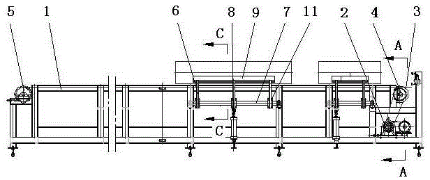
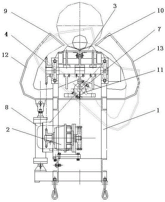
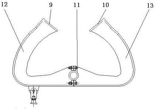
[0013] As shown in the drawings, an automatic log stacking device is characterized in that a frame 1 is provided, and a linear moving device and a turning device are arranged on the frame 1. The linear moving device includes a moving motor 2, a supporting wheel 3, The supporting wheel shaft, the driving shaft, the driven shaft, the driving sprocket 4, the driven sprocket 5 and the chain, and the turning device includes a turning frame 6, a turning shaft 7, a turning cylinder 8, an outer turning supporting plate 9 and an inner turning supporting plate 10. Supporting wheel shafts are horizontally arranged on the frame 1 sequentially. One end of the frame 1 is provided with a driving shaft, and the other end is provided with a driven shaft. The supporting wheel shaft is provided with a supporting wheel 3, and the supporting wheel shaft is provided with a sprocket , the driving sha...
PUM
Abstract
The invention relates to an automatic raw wood stacking device and belongs to the technical filed of wood-working machinery. The automatic raw wood stacking device is characterized in that the device is provided with a rack, wherein the rack is provided with a linear moving device and a turnover device, the linear moving device comprises a moving motor, a riding wheel, a riding wheel shaft, a driving shaft, a driven shaft, a driving chain wheel, a driven chain wheel and a chain, the turnover device comprises a turnover frame, a turnover shaft, a turnover cylinder, an outer turnover support plate, and an inner turnover support plate, the riding wheel shaft is arranged on the rack, the riding wheel is arranged on the riding wheel shaft, the turnover shaft is arranged below the riding wheel, the turnover frame is composed of a shaft sleeve, an outer turnover frame and an inner turnover frame, the shaft sleeve is arranged on the turnover shaft, one side of the shaft sleeve is fixedly connected with the outer turnover frame, and the other end of the shaft sleeve is fixedly connected with the inner turnover frame; the upper end of the outer turnover frame is fixedly connected with the outer turnover support plate, the lower end of the outer turnover frame is connected with the rack through the turnover cylinder, and the upper and of the inner turnover frame is fixedly connected with the inner turnover support plate. The automatic raw wood stacking device provided by the invention has the advantages of being novel in structure, high in automation degree, quick in stacking speed, safe to operate, low in employment cost, and the like.
Description
technical field [0001] The invention relates to the technical field of woodworking machinery, in particular to an automatic log stacking device. Background technique [0002] At present, after sawing large-scale logs to a standard length, due to their large diameter and heavy weight, cranes and at least 1-2 workers are usually used to stack the sawn logs. The disadvantages are: slow stacking speed, The danger is high, the labor intensity of the operator is high, and the labor cost is high, which cannot meet the needs of modern production. Contents of the invention [0003] The purpose of the present invention is to solve the above-mentioned deficiencies in the prior art, and provide an automatic log stacking device with novel structure, high degree of automation, fast stacking speed, safe operation, low labor intensity and low labor cost. [0004] The technical solution adopted by the present invention to solve its technical problems is: [0005] An automatic log stackin...
Claims
Application Information
Patent Timeline
Application Date:The date an application was filed.
Publication Date:The date a patent or application was officially published.
First Publication Date:The earliest publication date of a patent with the same application number.
Issue Date:Publication date of the patent grant document.
PCT Entry Date:The Entry date of PCT National Phase.
Estimated Expiry Date:The statutory expiry date of a patent right according to the Patent Law, and it is the longest term of protection that the patent right can achieve without the termination of the patent right due to other reasons(Term extension factor has been taken into account ).
Invalid Date:Actual expiry date is based on effective date or publication date of legal transaction data of invalid patent.