
Small-sized diaphragm pump simulation frequency changing system and control method thereof

A frequency conversion system and diaphragm pump technology, applied in pump control, liquid variable capacity machinery, machines/engines, etc., can solve the problems of not improving the recovery rate, differences in individual parameters of diaphragm pumps, changes in medium circulation flow rate, etc., to simplify the quality. The effect of controlling difficulty

Active Publication Date: 2014-03-12
厦门锐思捷水纯化技术有限公司
View PDF9 Cites 12 Cited by
  • Summary
  • Abstract
  • Description
  • Claims
  • Application Information

AI Technical Summary

Problems solved by technology

[0003] For a small reverse osmosis pure water system using this type of pump, the water temperature drops sharply in winter, and the pure water output of the reverse osmosis membrane will also drop significantly with the lower water temperature. The output of the pump increases the working pressure of the reverse osmosis membrane, but the constant frequency pump cannot achieve this without increasing the recovery rate. Increasing the recovery rate will affect the life of the reverse osmosis membrane and reduce the quality of the produced water, and manual intervention is required. Adjustment;
[0004] For circulating water systems that require a constant flow rate, individual parameter differences and output instability of this type of diaphragm pump, as well as changes in the pressure loss of pump outlet components will lead to changes in the medium circulation flow rate, making it difficult to achieve the goal of constant flow rate

Method used


Image

  • Small-sized diaphragm pump simulation frequency changing system and control method thereof
  • Small-sized diaphragm pump simulation frequency changing system and control method thereof

Examples


Embodiment Construction

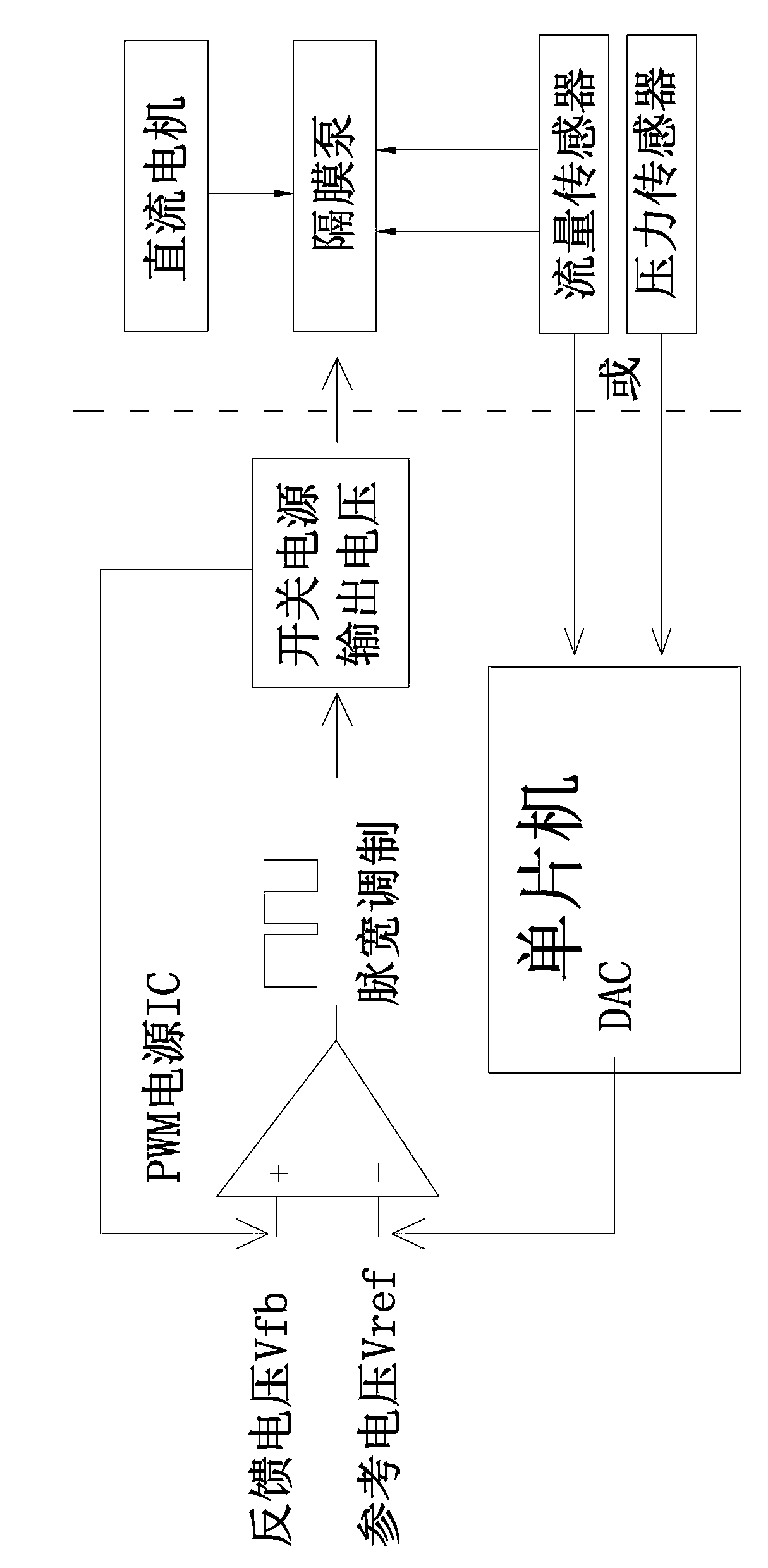
[0023] Such as figure 1 The shown small diaphragm pump simulates the frequency conversion system. The system includes a PWM switching power supply. The PWM switching power supply is respectively connected to a diaphragm pump driven by a DC motor and a single-chip microcomputer with a DAC conversion circuit; a flow sensor is arranged between the diaphragm pump and the single-chip microcomputer. or pressure sensor.

[0024] The output voltage of the PWM power supply IC of the PWM switching power supply is determined by the reference voltage Vref and the feedback voltage Vfb. The reference voltage Vref is provided by the DAC conversion circuit of the microcontroller; the feedback voltage Vfb is taken from the output terminal of the PWM switching power supply. The output end of the PWM switching power supply is connected to the power input end of the diaphragm pump.

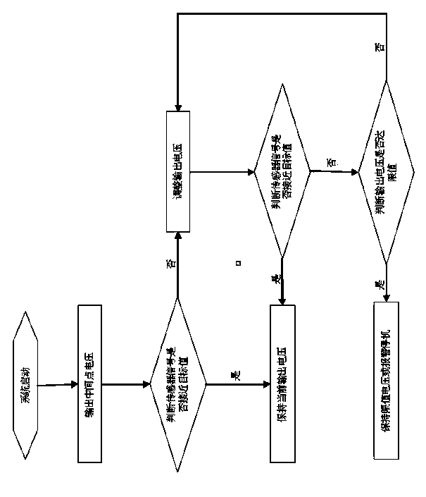
[0025] Such as figure 2 The small diaphragm pump simulation frequency conversion control method shown includes ...


PUM


Abstract

Disclosed are a small-sized diaphragm pump simulation frequency changing system and a control method thereof. The small-sized diaphragm pump simulation frequency changing system comprises a PWM switching power source, the PWM switching power source is connected with a diaphragm pump driven by a direct-current motor and a single-chip microcomputer provided with a DAC conversion circuit, and a flow sensor or a pressure sensor is arranged between the diaphragm pump and the single-chip microcomputer. Compared with a traditional method, the control method is characterized in that a multi-voltage-output control circuit is used, meanwhile, the pressure sensor or the flow sensor are additionally arranged behind the pump for monitoring the force output state of the pump, similar frequency changing effects are realized through cooperative control of the pressure sensor or the flow sensor and output voltages of the circuit, and therefore the work target of realizing constant voltages or constant currents is achieved. By means of the small-sized diaphragm pump simulation frequency changing system and the control method of the small-sized diaphragm pump simulation frequency changing system, power consumption of the water pump can be automatically adjusted to be at the best level, ultrapure water indexes can be stabilized, the water taking flow speed is kept to be constant, the system yield is kept to be stable and environmental friendliness and energy conservation are realized.

Description

technical field [0001] The invention relates to a small-scale water purification system, in particular to a small-scale fluid pressurization or circulation system. Background technique [0002] In existing small-scale fluid pressurization systems (such as reverse osmosis pure water machines) or circulation systems (such as laboratory ultra-pure water systems), small diaphragm pumps driven by DC brushed motors are commonly used to drive pumps, and these pumps Because it adopts a brushed motor and works at a fixed power, like most constant frequency pumps, its head-water volume is in a nearly inversely proportional curve. When the inlet pressure of the pump changes, or the pressure loss of the components behind the pump changes, it often means that its water volume and lift will also change, which cannot adapt to various conditions. Out of adaptive power adjustment requirements. At the same time, even with the same type of pump, it is difficult to ensure the consistency of i...

Claims


Application Information

Patent Timeline
Patent Type & Authority Applications(China)
IPC IPC(8): F04B49/06
Inventor 岳勇斌
Owner 厦门锐思捷水纯化技术有限公司
Learn More