Defoaming pump

A pump body and pump shaft technology, which is used in the field of anti-foam pumps to achieve the effect of eliminating foam

Inactive Publication Date: 2014-03-12
ANHUI YINLONG PUMP VALVE
View PDF4 Cites 2 Cited by
  • Summary
  • Abstract
  • Description
  • Claims
  • Application Information

AI Technical Summary

Problems solved by technology

[0003] The purpose of this invention is to provide a defoaming pump to solve the problem

Method used


Image

  • Defoaming pump

Examples


Embodiment Construction

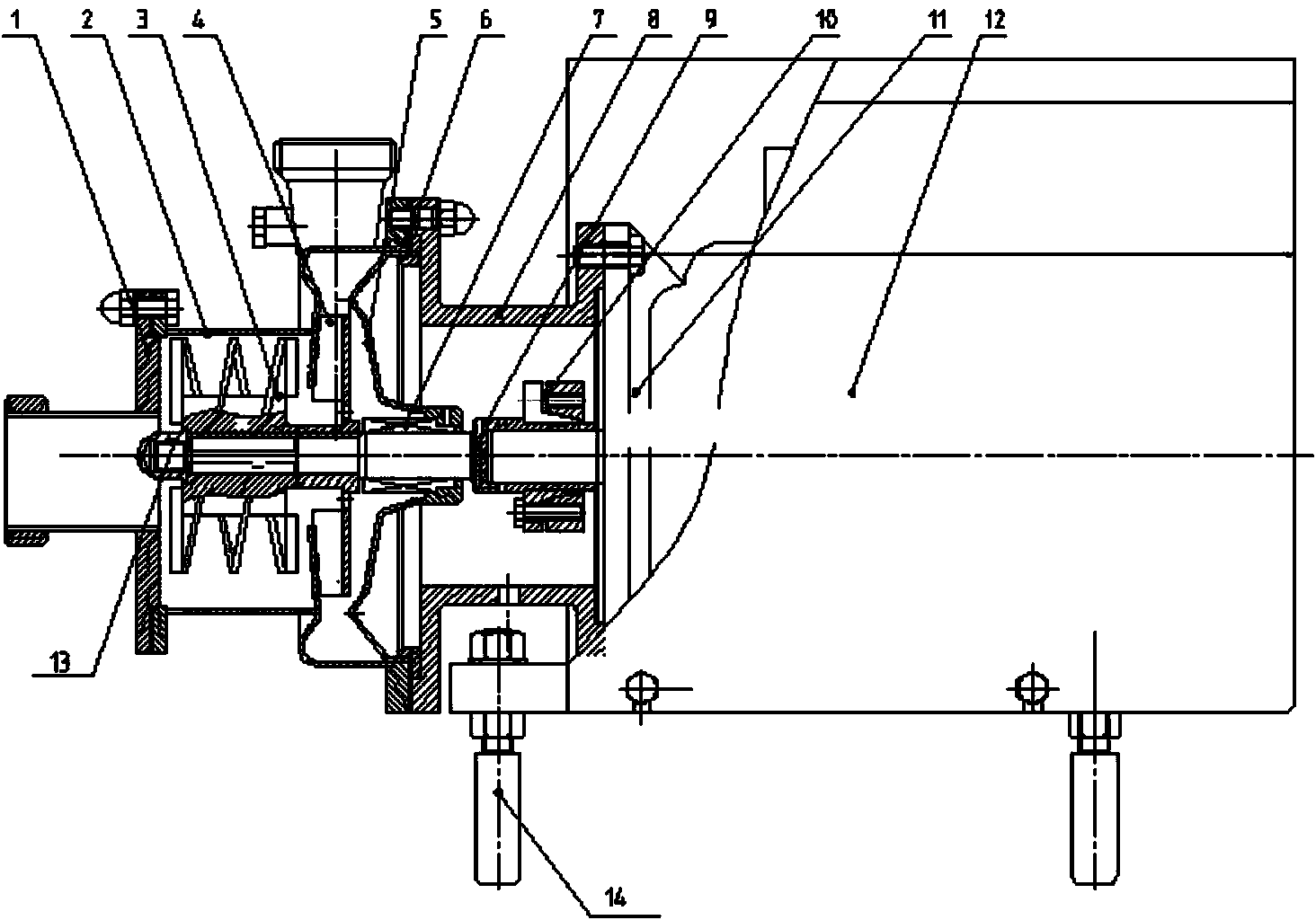
[0013] Such as figure 1 As shown, a defoaming pump includes a front cover 1, a pump body 2, a screw impeller 3, an impeller 4, a pump cover 5, an O-ring 6, a mechanical seal 7, a coupling body 8, a pump shaft 9, and a coupling Components 10, motor 11, protective cover 12, impeller nut 13 and supporting legs 14, the helical impeller 3 is installed on the pump shaft 9 in the pump body 2, the front end of the pump body 2 is equipped with a front cover 1, and the rear of the helical impeller 3 is installed There is an impeller 4, a pump cover 5 is installed at the rear end of the pump body 2, an O-ring 6 is connected with the pump cover 5, a mechanical seal device 7 is installed on the pump shaft 9 behind the impeller 4, and an impeller nut 13 is installed at the front end of the pump shaft 9 The end of the pump shaft 9 is installed on the motor 11 through the coupling assembly 10, the pump body 2 is installed on the motor 11 through the coupling body 8, the motor 11 is equipped w...


PUM


Abstract

The invention discloses a defoaming pump. The defoaming pump comprises a front cover, a pump body, a spiral impeller, a pump cover, an O-shaped ring, a mechanical sealing device, a connector, a pump shaft, a coupler component, a motor, a protective cover, an impeller nut and supporting legs, wherein the spiral impeller is arranged on the pump shaft of the pump body; the front cover is arranged at the front end of the pump body; the impeller is arranged behind the spiral impeller; the pump cover is arranged at the rear end of the pump body; the O-shaped ring is connected with the pump body; the pump shaft behind the impeller is provided with the mechanical sealing device; the front end of the pump shaft is provided with the impeller nut, and the tail end of the pump shaft is arranged on the motor by the coupler component; the pump body is arranged on the motor by the connector; the protective cover is arranged outside the motor; and the supporting legs are arranged at the bottom part of the protective cover. The defoaming pump disclosed by the invention has the advantages that the foam separating effect is good, gas-contained liquid can be conveyed, the working performance is high and the use is safe.

Description

technical field [0001] The invention relates to a pump for liquid delivery, in particular to a defoaming pump. Background technique [0002] Traditional centrifugal pumps are only suitable for transporting liquids without gas. If the medium contains gas, the work will be interrupted. The design of this product is mainly for the transportation of medium with high hygiene requirements and containing gas or bubbles. Contents of the invention [0003] The object of the present invention is to provide a defoaming pump to solve the problem that traditional centrifugal pumps are only suitable for transporting liquids without gas. [0004] In order to solve the above problems, the technical solution adopted in the present invention is: [0005] A defoaming pump, including a front cover, a pump body, a helical impeller, an impeller, a pump cover, an O-ring, a mechanical seal, a coupling body, a pump shaft, a coupling assembly, a motor, a protective cover, an impeller nut and a sup...

Claims


Application Information

Patent Timeline
IPC IPC(8): F04D7/02F04D29/00
Inventor 吴杰徐俊东汪云孟金华费东荣钱忠徐文海
Owner ANHUI YINLONG PUMP VALVE
Why Eureka
Try Eureka