Combined-type transition cable leading cage based on cable leading below bridge

A combined type and cable technology, which is applied in the direction of electrical components, pipe supports, pipes/pipe joints/pipe fittings, etc., can solve the problems of too small bending radius of cables, failure of positioning of cables, increased side pressure, etc., to solve the problem of bending radius , safe use, and cost-saving effects

Active Publication Date: 2014-03-12
STATE GRID CORP OF CHINA +2
View PDF6 Cites 3 Cited by
  • Summary
  • Abstract
  • Description
  • Claims
  • Application Information

AI Technical Summary

Problems solved by technology

However, the circular pulley needs to be arranged through complex calculations and on-site simulations. If a local deviation occurs during the setting process, the cable bending radius is too small, the side pressure increases, and the cable is damaged; in

Method used


Image

  • Combined-type transition cable leading cage based on cable leading below bridge
  • Combined-type transition cable leading cage based on cable leading below bridge
  • Combined-type transition cable leading cage based on cable leading below bridge

Examples


Embodiment Construction

[0022] Best practice:

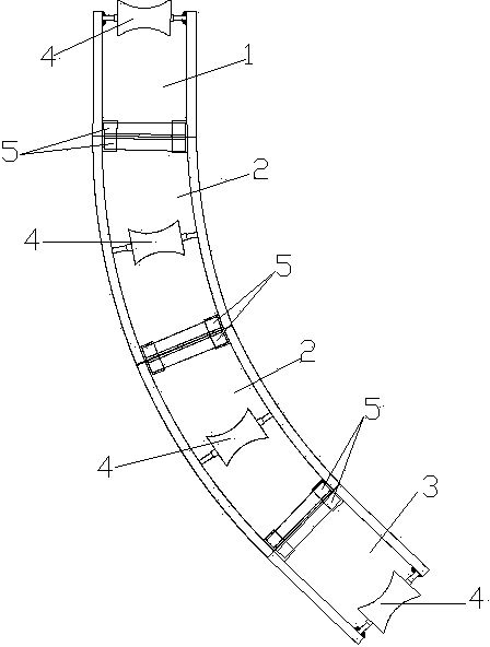
[0023] Refer to attached figure 1 , the combined transition lead cage based on the lead cable under the cable bridge, including a lead lead cage 1, a tail lead cage 2 and more than two middle lead lead cages 3. The first cable cage 1 , the tail cable cage 2 and each intermediate cable cage 3 are composed of a pulley frame 4 , an angle steel frame 5 and steel pipes.

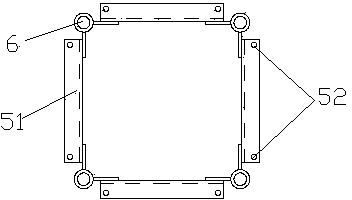
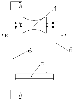
[0024] Refer to attached figure 2 And attached image 3 , the structure of the first cable cage 1 and the tail cable cage 2 is the same, the steel pipe 6 used is a straight steel pipe, the first cable cage 1 and the tail cable cage 2 are made of straight steel pipes 6 and respectively located in the straight Type steel pipe 6 two ends and a pulley frame 4 that is connected with this straight steel pipe 6, an angle steel frame 5 forms. The structure of concrete pulley frame 4 refers to attached Figure 4 , the pulley frame is a square planar frame consisting of four sides and four vert...


PUM


Abstract

The invention relates to a technique of cable leading below a bridge in bridge cable projects, in particular to a combined-type transition cable leading cage based on cable leading below the bridge. The cable leading cage is structurally characterized by comprising a head section cable leading cage body, a tail section cable leading cage body and a plurality of middle section cable leading cage bodies, an angle steel framework of the head section cable leading cage body is fixedly connected with an angle steel framework of one end of each middle section cable leading cage body by the fact that bolts are screwed into connection screw holes, according to the transition cable leading cage, an arc-shaped middle section is formed due to the fact that the multiple middle section cable leading cage bodies are connected in an end-to-end mode, and the angle steel framework of the other end of the last middle section cable leading cage is fixedly connected with an angle steel framework of the tail section cable leading cage body through bolts. The cable leading cage has the advantages that modularized on-site installation is adopted, construction operations are easy and convenient to achieve, time and labor are saved, efficiency is high, safety is good, the use range is wide, the cables are all led in a cage-shaped framework, the cable leading cable performs the function of surrounding the cables and accordingly the cable are not prone to being damaged.

Description

technical field [0001] The invention relates to a technology for leading cables under the bridge in bridge and cable engineering, in particular to a combined transitional leading cable cage based on the leading cables under the cable bridge. Background technique [0002] In the bridge cable project of the bridge, the cable bridge is suspended and fixed on both sides of the bridge belly, and the cable is led from the bridge deck to the bridge belly cable bridge below the bridge deck. Outside the platform, in order to solve the control problems such as bending radius, side pressure, and damage during the laying of the cable under the bridge, the general method is to set up a steel pipe frame on the lower bridge operating platform, and install ring blocks at multiple points in the frame to control. However, the circular pulley needs to be arranged through complex calculations and on-site simulations. If a local deviation occurs during the setting process, the cable bending radi...

Claims


Application Information

Patent Timeline
IPC IPC(8): F16L3/00
CPCH02G3/0406H02G3/0456
Inventor 林贤浩黄鹏贤庄英平林光如王容华陈强
Owner STATE GRID CORP OF CHINA
Why Eureka
Try Eureka