Uniform temperature plate and manufacturing method thereof

A technology of vapor chamber and side plate, which is applied in the direction of manufacturing tools, cooling/ventilation/heating transformation, lighting and heating equipment, etc., which can solve the problem of dirty working environment of the production line, easy peeling of solder, and unevenness of the periphery of the vapor chamber Status and other issues, to achieve the effect of keeping the working environment clean

Inactive Publication Date: 2014-03-12
邱维廉 +1
View PDF11 Cites 4 Cited by
  • Summary
  • Abstract
  • Description
  • Claims
  • Application Information

AI Technical Summary

Problems solved by technology

[0004] However, the vapor chamber manufactured by such a manufacturing method has the following disadvantages: first, a flange will be formed on the periphery of the chamber, which is a product of butt joint pressing and welding, so that the periphery of the chamber will Unable to be in a flat state, detracting from its appearance
Second, the solder is welded on the two border edges of the lower shell and the upper shell in the form of coating welding, so during the welding process, the solder is easy to drip onto the work table and the working environment of the entire production line becomes messy
Third, the solder after soldering is in a suspended state, so the solder is easy to peel off and reduce its sealing effect

Method used


Image

  • Uniform temperature plate and manufacturing method thereof
  • Uniform temperature plate and manufacturing method thereof
  • Uniform temperature plate and manufacturing method thereof

Examples


Embodiment Construction

[0049] The detailed description and technical content of the present invention will be described as follows with reference to the accompanying drawings, but the accompanying drawings are for illustrative purposes only and are not intended to limit the present invention.

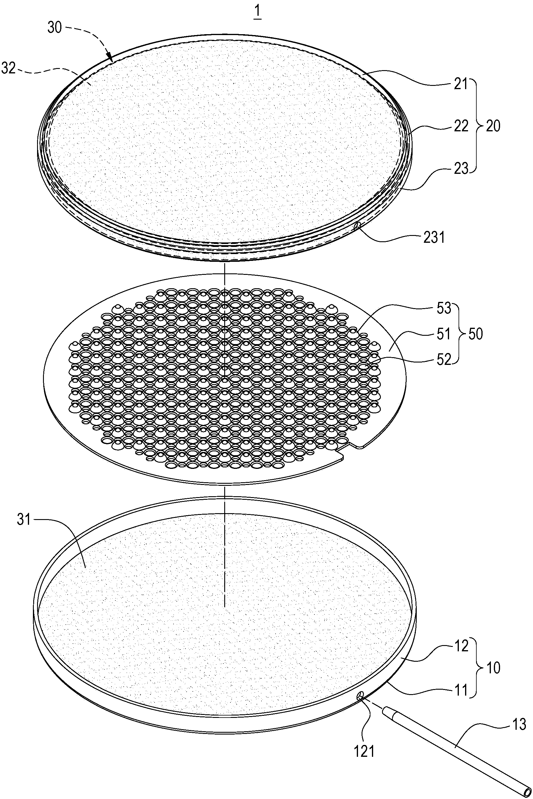
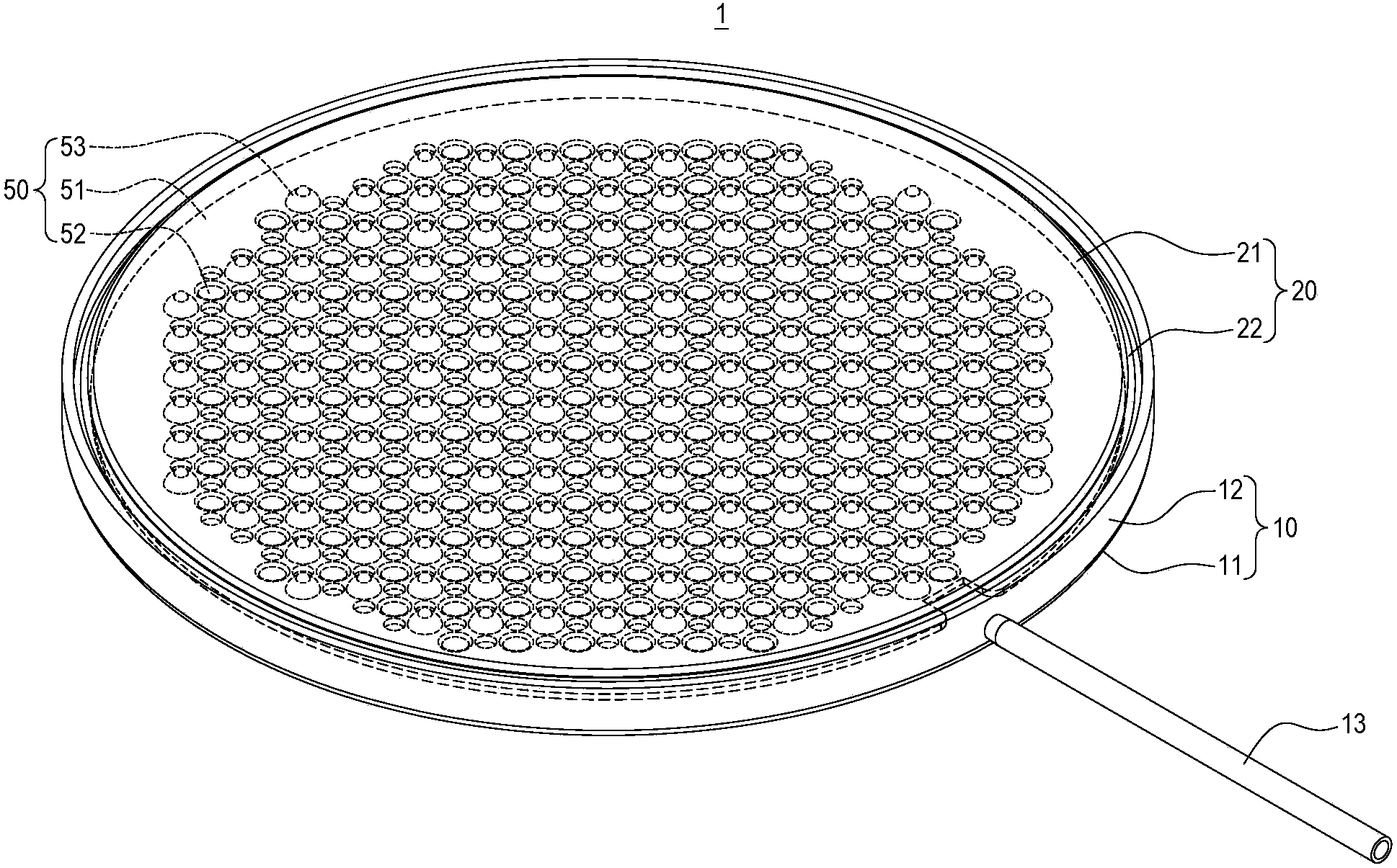
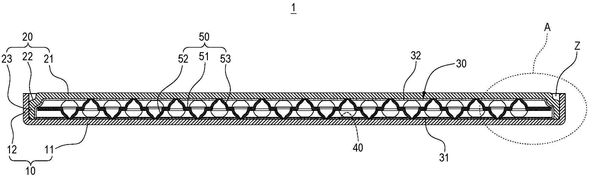
[0050] Please refer to Figure 1 to Figure 5 , The invention provides a vapor chamber and a manufacturing method thereof. The vapor chamber 1 of the present invention includes: a lower casing 10 , an upper casing 20 , a capillary structure 30 , a working fluid 40 , and a supporting structure 50 .

[0051] The lower casing 10 is roughly disc-shaped and can be made of metal or ceramic material. The lower casing 10 is made to have a bottom plate 11 and a lower side plate 12 extending on the periphery of the bottom plate 11. The lower side plate 12 has a divider. The air hole 121 is used for a degassing pipe 13 to pass through. In addition, a lower capillary portion 31 is sintered on the upward facing surface o...


PUM


Abstract

The invention discloses a uniform temperature plate and a manufacturing method of the uniform temperature plate. The uniform temperature plate comprises a lower shell body, an upper shell body, a capillary structure and work fluid, wherein the lower shell body is provided with a bottom plate and a lower side plate extending to the periphery of the bottom plate, the upper shell body is provided with a top plate, an annular groove formed in the outer edge of the top plate and an upper side plate extending to the periphery of the annular groove, the upper shell body covers the lower shell body so that the upper side plate can abut against the lower side plate, and a solder containing area is arranged between the annular groove and the lower side plate in a surrounding mode. Through the structure, solder will not drip to the periphery of the uniform temperature plate in the welding process, and the solder is not stripped off easily after welding is finished.

Description

technical field [0001] The invention relates to a uniform temperature plate and a manufacturing method thereof, in particular to a uniform temperature plate with a solder accommodation area and a manufacturing method thereof. Background technique [0002] With the rapid development of science and technology and the thinning of electronic products, many types of vapor chambers have been developed to conduct and dissipate heat from electronic heating elements. [0003] The current manufacturing method of the vapor chamber is to butt and cover the lower shell and an upper shell, then align and press the periphery of the lower shell and the periphery of the upper shell, and finally seal the pressed edge with solder Seal it up. [0004] However, the vapor chamber manufactured by such a manufacturing method has the following disadvantages: first, a flange will be formed on the periphery of the chamber, which is a product of butt joint pressing and welding, so that the periphery o...

Claims


Application Information

Patent Timeline
Patent Type & Authority Applications(China)
IPC IPC(8): F28D15/04H05K7/20B23K1/00
Inventor 王勤文
Owner 邱维廉
Why Eureka
Try Eureka